Gravity sewer gradients in the UK: minimum and maximum slopes — BS EN 752 and Sewerage Sector Guidance
Quick answer
Gravity sewer gradient is chosen for self-cleansing, not just to move water downhill: BS EN 752 and the sewerage undertaker's Design and Construction Guidance require a minimum velocity (commonly around 0.75 m/s) at the design flow. The 1-in-DN rule of thumb gives a quick starting slope, but only the velocity check under BS EN 752 is the defensible minimum; above roughly 3–5 m/s, abrasion and air entrainment set the practical maximum.
Note: this article explains the design logic. Mind the scope: a public sewer (offsite network) is governed by BS EN 752 together with the sewerage undertaker's Design and Construction Guidance (DCG) / Sewerage Sector Guidance — successor to Sewers for Adoption 7th ed.; building drainage within the curtilage falls under Building Regulations Approved Document H, not the public-sewer framework — do not conflate the two in the design statement. Concrete numeric values must always be checked against the current edition of the relevant standard and the undertaker's guidance. Verify technically before publishing.
The slope of a gravity sewer is a balance, not a single correct number. Too flat and solids settle; too steep and you either bury the pipe needlessly or exceed sensible flow velocities. This guide explains the design logic so the numbers stop being arbitrary.
Why gradient matters
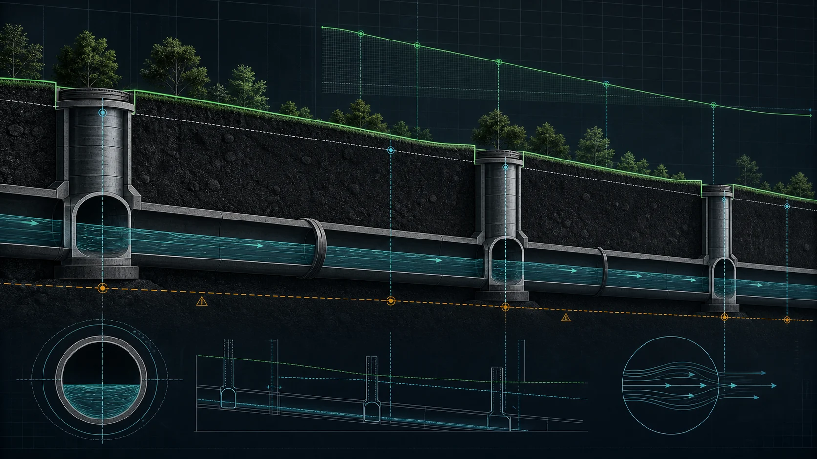
A gravity sewer is sized for part-full flow. The slope sets the flow velocity, and velocity decides two things that matter every day on a project:
- Self-cleansing — the flow must be fast enough, often enough, to move grit and solids rather than let them deposit.
- Pipe and structure protection — too high a velocity, particularly with abrasive flow, shortens the life of the invert and downstream structures.
For a public sewer the framework is BS EN 752 with the sewerage undertaker's Design and Construction Guidance; Building Regulations Approved Document H covers building drainage and the connection within the property, not the public sewer — keep the two scopes separate in the design statement. These frameworks express the self-cleansing requirement as a minimum velocity at a defined flow condition (referenced to a design flow, not the mean flow), commonly on the order of 0.75 m/s. Treat the value here as the principle; the binding figure is in the current edition of the standard and the undertaker's guidance.
The minimum slope
In practice two approaches coexist:
- Velocity-based — pick the slope that delivers the minimum self-cleansing velocity for the design flow, using Manning or Colebrook–White. This is the defensible method and the one a reviewer expects on larger or critical sewers.
- Rule of thumb — the well-known 1/DN guide: a minimum slope of roughly
1 ÷ pipe diameter in mm. A DN200 sewer → about 1/200 (5 ‰), DN300 → about 1/300 (3.3 ‰). It is a sanity check and a starting point, not a substitute for the velocity check on demanding reaches.
Important for UK practice: the 1/DN rule serves pre-sizing, but the design must be defended by the self-cleansing velocity check at the design flow under BS EN 752 and the undertaker's guidance — that is the auditable proof, not the rule of thumb itself.
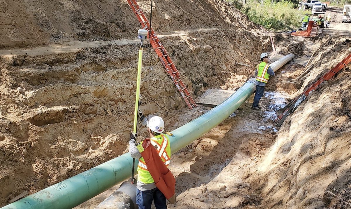
The flatter the sewer, the more sensitive it is to construction tolerances: a few centimetres of invert error over a long reach can wipe out a shallow design gradient. That is exactly why the longitudinal profile — invert levels at every manhole, gradient per reach, cover depth — has to be exact, not approximate.
The maximum slope
There is rarely a single hard maximum, but there are limits:
- Velocity — above roughly 3–5 m/s (standard- and material-dependent: lined concrete, vitrified clay or ductile iron tolerate more than plain plastics) abrasion and air entrainment become design concerns; energy dissipation or a backdrop manhole may be required.
- Cover and earthworks — chasing terrain too aggressively buries the pipe deeper than necessary and inflates excavation. A steep reach followed by a backdrop (drop) connection in a manhole is often cheaper and cleaner than one continuous steep run. In the UK's mild climate minimum cover is driven primarily by traffic loading and structural protection (typically of the order of 0.9 m in gardens and 1.2 m under roads per the undertaker's DCG — verify against the current edition), not by frost depth.
What this means for the profile
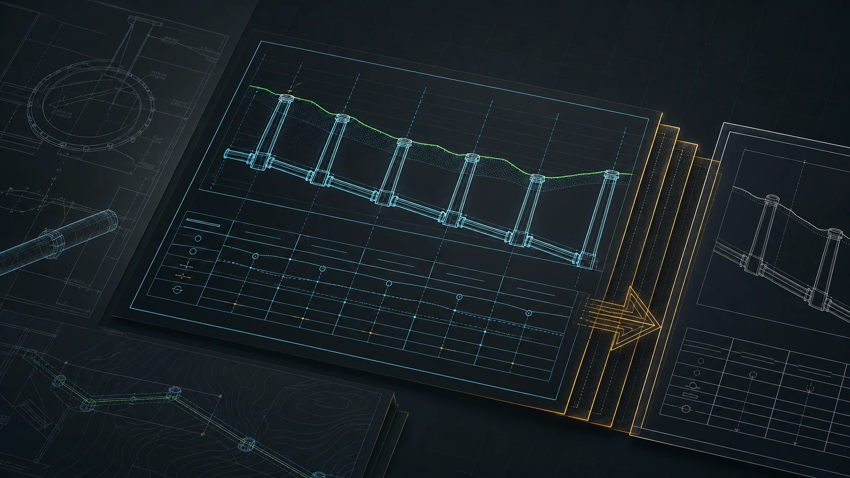
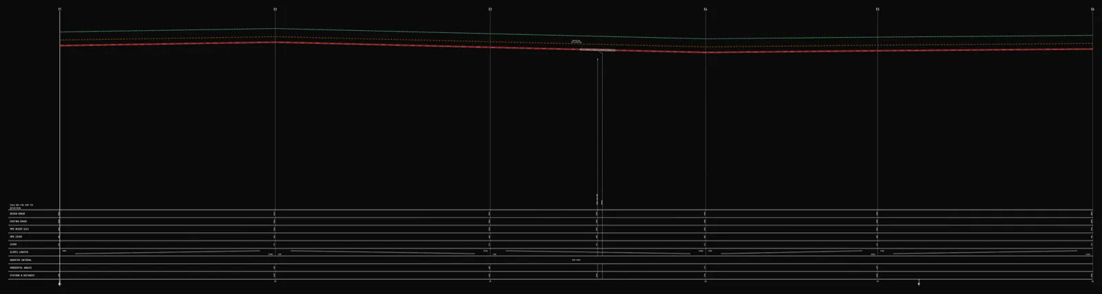
Choosing gradients is only half the work; the other half is showing them correctly on the long section so the design survives review and construction:
- invert level resolved at every manhole,
- gradient per reach in ‰ or %, consistent with the lengths,
- backdrop connections where the invert step demands them,
- cover depth verified along the whole route.
Run the hydraulic checks (velocity, fill ratio, diameter) in a dedicated calculator such as KalkulatorPro, then bring the resulting gradients into the drawing. Producing the long section itself — and a clean, deliverable DXF from it — is exactly what Altivo does step by step.
Frequently asked questions
What is the minimum slope for a gravity sewer? There's no single fixed number — the minimum is set by self-cleansing velocity, not just moving water downhill. Under BS EN 752 and the sewerage undertaker's Design and Construction Guidance, the slope must deliver a minimum velocity at the design flow, commonly on the order of 0.75 m/s. The 1-in-DN rule of thumb (roughly 1 divided by the pipe diameter in mm) gives a starting slope, but the velocity check is the defensible minimum.
What is the 1-in-DN rule for sewer gradient? The 1-in-DN rule is a quick pre-sizing guide: minimum slope of roughly 1 divided by the pipe diameter in millimetres. A DN200 sewer gives about 1:200 (5 ‰) and a DN300 about 1:300 (3.3 ‰). It's a sanity check and a starting point, not a substitute for the self-cleansing velocity check at the design flow, which is the auditable proof a reviewer expects.
What is the maximum slope for a sewer pipe? There is rarely a single hard maximum, but above roughly 3 to 5 metres per second abrasion and air entrainment become design concerns. The exact limit is material-dependent: lined concrete, vitrified clay or ductile iron tolerate more than plain plastics. Where terrain is steep, a backdrop or drop connection in a manhole is often cheaper and cleaner than one continuous steep run, and energy dissipation may be required.
Which standard governs UK public sewer gradients? For a public sewer the framework is BS EN 752 together with the sewerage undertaker's Design and Construction Guidance, the successor to Sewers for Adoption. Building drainage within the property falls under Building Regulations Approved Document H instead. Keep the two scopes separate in the design statement and check concrete values against the current edition of the relevant standard.
Try Altivo free — 14 days, no card required.
Related articles
Minimum sewer slope (gradient) by pipe size: the 1-in-DN table
Minimum gradient per DN for gravity public sewers using the 1-in-DN rule (Maguire’s Rule) — as a 1:DN ratio, % and mm/m. How it differs from UK 1:40/1:80 private-drainage falls and from self-cleansing velocity (EN 752).
Sewer long section to DXF — step by step
From field coordinates to a CAD-ready longitudinal profile of a gravity sewer. A concrete walkthrough: import, gradients, manholes, drop connections, dual-scale DXF export.
Underground cable long section — power and telecom cable routes
How to draw the longitudinal profile of a buried power or telecom cable route: minimum burial depth by voltage class, crossings, protective ducting, warning tape and a DXF export — in the browser, no CAD.
District heating long section — preinsulated pipe in profile
How to draw the longitudinal profile of a district heating network with preinsulated bonded pipe: two diameters (carrier and casing), cover to the casing crown, leak detection, crossings, the profile table and a DXF and IFC export — in the browser, no CAD.
Ready to design without the pain?
Altivo is the fastest way to produce a clean DXF. Try it today.
Open the free app