Underground cable long section — power and telecom cable routes
Quick answer
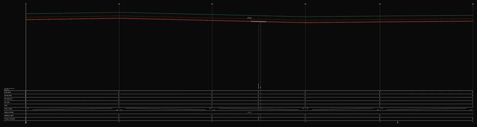
An underground cable long section (power or telecom) has no gravity gradient like a sewer and no pressure class like gas — depth is set by minimum burial-depth guidance for the cable's voltage class or type. UK DNOs typically require 450mm cover for LV cables under gardens, 600mm under driveways/roads and 1000mm for HV; telecom ducts follow Street Works UK depths of roughly 250–600mm depending on surface. The profile documents crossings, protective ducting and warning tape.
An underground cable long section — whether it's a power cable or a telecom duct — follows different rules from a pipe profile. There's no gravity gradient like a sewer, because a cable doesn't carry anything that needs to flow downhill. There's no pressure class or control strip like a gas main either. What actually governs the cable's position in the ground is minimum burial depth for its voltage class or cable type, crossings with other buried utilities, and mechanical protection wherever normal cover can't be maintained. Here's the path from route coordinates to a deliverable DXF.
How a cable profile differs from a pipe profile
- Gravity sewer — the invert level follows a designed gradient; you design the slope, and depth is a consequence of it.
- Water and gas mains — both follow the ground at roughly constant cover, but the governing criterion differs (frost depth for water, regulation and control-strip requirements for gas).
- A cable route — also follows the ground at roughly constant cover, but the criterion is minimum burial depth for the voltage class (power) or duct depth guidance (telecom) — not frost depth, not pressure. There's no gradient to design at all: the only thing that matters is that cover above the cable doesn't drop below the minimum anywhere along the route.
How deep does a power cable need to go
There's no single depth that applies "everywhere" — burial depth for power cables is set by the network operator (DNO) under BS 7671 wiring regulations and each DNO's own connection standards (e.g. ENA member guidance). Typical figures published by UK DNOs for direct-buried cable or duct:
| Cable class | Gardens / private land | Driveways / roads | Cultivated agricultural land |
|---|---|---|---|
| LV (up to ~400/230V) | 450mm | 600mm | 750mm (min.) |
| HV / 11kV+ | 1000mm (or per DNO spec) | 1000mm (or per DNO spec) | 1000mm (or per DNO spec) |
Where the ground is soft (repeated vehicle or machinery loading, frost heave, settling), depths are often increased by roughly 400mm beyond the base figure. Wherever the standard depth can't be kept — at a building entry, a crossing, or where the cable has to dodge another buried service — a shallower run is usually accepted provided it's protected with a duct or sleeve. Crossings with roads, rail, watercourses and other utilities are laid as close to a right angle as practical, with protection extending a margin on both sides of the crossing point.
How deep does a telecom cable need to go
Telecom cables and ducts (including fibre) follow a separate, generally shallower set of depths — historically set out in NJUG guidance, now maintained by Street Works UK. Typical figures: roughly 250–350mm in footpaths or private land, and 450–600mm under roads and verges, with a duct crossing a carriageway usually laid at 600mm or more. The exact figure is confirmed with the network operator or the highway authority. A key difference from power cables: telecom cable — especially fibre, which carries no metallic conductor — usually isn't detectable by electromagnetic locators, so a detectable warning tape with a metallic tracer wire or foil is laid above the duct regardless of depth to make it findable later.
Two separate network kinds, one profile logic
In Altivo's schema, power cable and telecom cable are two separate, first-class network kinds — alongside water, sewer, pressure sewer, gas and district heating. Both share the same trait: no gravity gradient, no pressure class. What sets them apart is what else they carry:
- Electric networks carry electrical parameters on top of the geometry — single-phase or three-phase circuit, power factor (cosφ), conductor cross-section and material (Cu/Al), insulation (PVC/XLPE), and a maximum allowable voltage drop. Altivo runs a voltage-drop calculation along the route and flags the furthest load if it exceeds your set limit — a check none of the other network kinds in the app performs.
- Telecom networks reuse the same node, segment and depth geometry, with no extra electrical calculation — what matters is the route, the cover, and the crossings.
That means one project can carry an LV feeder, a telecom duct running alongside it, and a crossing with a water main — each network kind with its own default depth and colour, so the profiles never get mixed up.
Crossings and protective ducting
Collisions with other buried utilities (water, sewer, gas, another cable) are marked as crossings with the collision level and chainage — they show up automatically on both the plan and the profile. Wherever cover can't be maintained, or the cable runs under a road, you add a protective duct — a range object spanning the relevant stretch of the route with its own diameter and length, drawn on the profile as a sleeve around the cable axis.
Warning tape
A warning tape is laid above the cable — power or telecom — usually 150–300mm above it, in a colour that identifies the utility (commonly yellow for electricity marked "ELECTRIC CABLE BELOW" per BS EN 12613, with telecom ducts marker-taped in their own operator colour). It's the last line of defence against accidental damage during later excavation. In Altivo, warning tape is a network property: you enable it, set its height above the cable and, if needed, the node range it covers — the profile then draws it automatically above the cable axis.
Step by step in Altivo
1. Points with chainage. Paste the cable route's node coordinates from a spreadsheet or a survey table — the separator is auto-detected. Set the network kind to Electric or Telecom; the default depth (0.8m) and material are sensible defaults to start from.
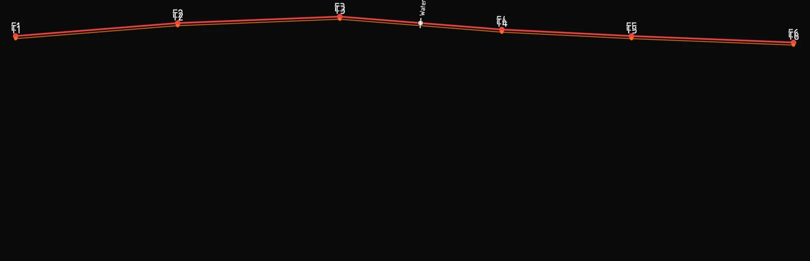
2. Ground levels. Fill in the existing ground level at each node — the cable route follows the ground at the set cover, so these levels drive how deep the cable ends up.
3. Burial depth. Adjust the depth so cover doesn't drop below the minimum from the table above — it's checked along the whole route, so you can see immediately where it gets too shallow.
4. Electrical parameters (power cables). In the network settings you set the circuit type (single or three-phase), cosφ, conductor cross-section and material, insulation, and the maximum allowable voltage drop — the profile then reports the current and the computed ΔU along the route.
5. Crossings and protective ducts. Mark collisions with other utilities as crossings with the collision level; add a protective duct from the object library under roads or wherever clearance is tight. More on the mechanics: How to add crossings and objects.
6. Warning tape. Enable it in the network settings and set the height above the cable — the profile draws it automatically along the whole route or a chosen node range.
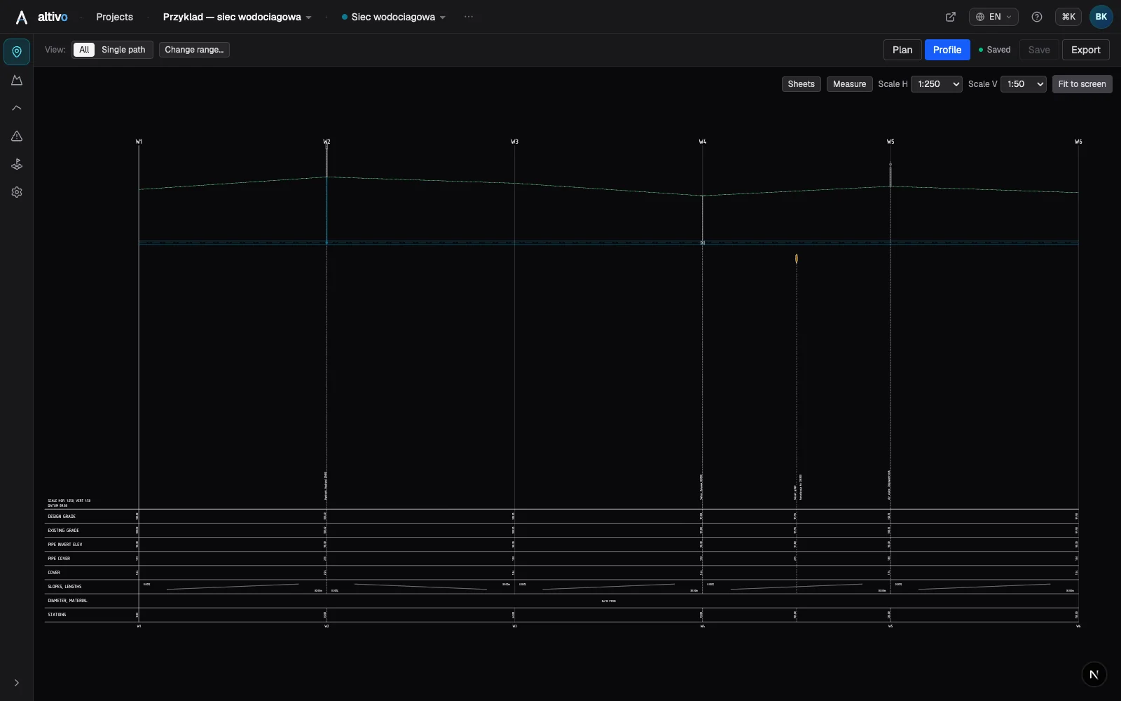
7. DXF export. A dual-scale file (e.g. 1:500 horizontal, 1:100 vertical) with clean, named layers and editable MText — ready to hand over without cleaning up layers first. Opens in AutoCAD, BricsCAD, ZWCAD or GstarCAD.
Frequently asked questions
What is the minimum burial depth for a low-voltage power cable? There's no single national number — it's set by the network operator (DNO) under BS 7671 guidance. Typical UK DNO figures for LV cables: 450mm under gardens or private land, 600mm under driveways and roads, 750mm under cultivated agricultural land, often increased by around 400mm in soft ground. HV cables usually need at least 1000mm or the DNO's own spec.
Does a telecom cable need to be buried as deep as a power cable? Not necessarily — telecom ducts follow separate, generally shallower depth guidance: roughly 250–350mm in footpaths or private land, 450–600mm under roads and verges. Because many telecom cables aren't detectable electromagnetically, a detectable warning tape with a metallic tracer wire is laid above regardless of depth.
How does a cable long section differ from a gas or water main profile? A water main sits below the frost line; a gas main is governed by pressure class and a control strip. A cable route has neither — depth follows burial-depth guidance for its voltage class or type, plus crossings. There's no gradient to design either.
Can several cables at different depths run in the same trench? Yes — e.g. an HV or LV feeder at one depth, a street-lighting cable shallower, telecom ducting alongside. In Altivo each is its own network with its own default depth.
How are crossings with other utilities marked on a cable profile? As a crossing with the collision level and chainage of the other utility, plus the required vertical clearance; under roads or wherever cover is tight, a protective duct spans the crossing with a margin on both sides.
What you get
A cable long section that's normally assembled by hand from a spreadsheet and a CAD drawing comes down here to a handful of deliberate design decisions — no install, in the browser, with an export ready to hand to the network operator.
See also: District heating long section, Water main long section to DXF, How to read a utility long section profile.
Try it free — 14 days, no card required.
Related articles
District heating long section — preinsulated pipe in profile
How to draw the longitudinal profile of a district heating network with preinsulated bonded pipe: two diameters (carrier and casing), cover to the casing crown, leak detection, crossings, the profile table and a DXF and IFC export — in the browser, no CAD.
Water main long section to DXF — step by step
How to draw a water main longitudinal profile: minimum cover vs frost depth, pipe centreline levels, valves and hydrants, crossings, the profile table and a clean dual-scale DXF export — in the browser, no CAD.

Sewer long section to DXF — step by step
From field coordinates to a CAD-ready longitudinal profile of a gravity sewer. A concrete walkthrough: import, gradients, manholes, drop connections, dual-scale DXF export.

How to draw a pipe long section (plan & profile) without building it in Civil 3D
Generate a utility long section — plan and profile, or "profile view" in Civil 3D — straight from your data, then finish the sheet in CAD: title block, revisions, annotations. A faster split of the work, not a CAD replacement.
Ready to design without the pain?
Altivo is the fastest way to produce a clean DXF. Try it today.
Open the free app