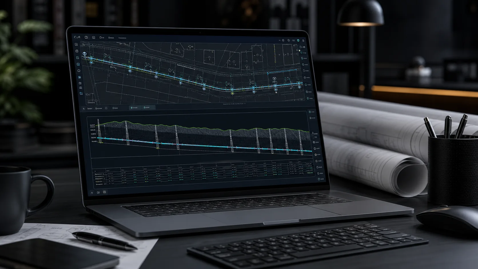
Quick answer
Online long section profile software lets you enter route points, ground levels and pipe levels in the browser and get a live-updating drawing: stationing, segment lengths, gradients and cover depth are calculated automatically from one data set, and the profile table stays in sync with the geometry. The finished long section exports as a DXF with named layers and editable text, ready to open in AutoCAD, BricsCAD, ZWCAD or GstarCAD for final annotation.
A long section is one of those drawings that must be technical, readable and easy to review at the same time. This applies to sewers, water mains, gas networks, service connections and shorter utility runs. One view has to show the route along the axis, ground levels, pipe levels, gradients, lengths, depths, diameters, material and crossing locations.
You can build it manually in CAD and a spreadsheet, but every design change increases the risk of a mismatch between the table, labels and geometry. Online long section profile software approaches the task differently: you enter or import the data in the browser, the drawing updates live, and the finished profile exports as DXF for further CAD work.
When an online tool makes sense
A browser-based profile tool is especially useful when you want to move quickly from survey or design data to a readable long section:
- you are preparing a service connection profile or a short network run,
- you need a consistent drawing and table without manually copying values,
- you work on different computers and do not want to install extra software,
- you want to generate a DXF that opens in AutoCAD, BricsCAD, ZWCAD, GstarCAD or another CAD package,
- you treat the profile as part of a wider drawing set that can later be annotated, framed or combined with other drawings.
It is not a replacement for a full CAD environment and it is not an automatic network designer. It is a focused tool for one job: building a profile from data, recalculating dependent values and exporting a CAD-ready drawing.
What data you need
A basic profile can be prepared from a small set of data. In most cases you need:
| Data | Purpose |
|---|---|
| route points or nodes | define the order of elements on the profile |
| distances or coordinates | make it possible to calculate stationing and segment lengths |
| ground levels | create the ground line and depths |
| pipe levels | define the pipe axis or invert |
| diameter and material | describe segments in the profile table |
| object type | marks a manhole, chamber, bend, crossing or fitting |
In practice the data can come from a survey, a map, a coordinate table, an earlier CAD drawing or a working spreadsheet. The important part is consistency: the same point order, the same units and a clear distinction between ground level and pipe level.
What the software calculates automatically
The main time saving is not just drawing a line. It is that dependent values are calculated from a single data set:
- stationing as cumulative distance along the route,
- segment lengths between consecutive points,
- gradient from the level difference and segment length,
- depth as the difference between ground and pipe level,
- values in the profile table below the drawing,
- labels for segments, nodes and crossings.
If you change a level, length or point location, the software recalculates the related values. The table, labels and profile geometry stay aligned. This matters during revisions, because one change on a long section often affects several places at once.
Gradient calculation example
Assume a sewer segment between two manholes:
| Point | Station [m] | Ground level [m] | Invert level [m] |
|---|---|---|---|
| S1 | 0.00 | 142.80 | 140.30 |
| S2 | 38.00 | 142.55 | 140.11 |
The segment gradient is:
(140.30 - 140.11) / 38.00 = 0.005 = 5.0 per mille
This is a simple spreadsheet formula, but the profile also needs a segment label, a correct scale, an updated table and geometry that matches the numbers. An online tool handles these together: the calculation, label and geometry all come from the same data.
Crossings and external elements
A useful profile often shows more than the designed pipe. It can also include coordination points: crossings with other utilities, culverts, roads, casing pipes, chambers, valves, hydrants or characteristic route points.
These elements can be entered as profile objects with their own location, level and label. They then appear in the right place on the drawing and in the table, instead of becoming loose notes added later in CAD.
Horizontal and vertical scale
Long sections usually use separate horizontal and vertical scales. The horizontal scale represents route length, while the vertical scale makes level differences visible. Common choices include:
- 1:500 horizontally and 1:100 vertically,
- 1:250 horizontally and 1:100 vertically,
- 1:1000 horizontally and 1:100 vertically for longer runs.
There is no single scale that fits every project. The drawing must be readable, labels must fit in the table, and the chosen scale must be clear to anyone who opens the DXF later.
DXF export
DXF is a practical exchange format because it opens in many CAD programs. For a long section, a good export should provide:
- ground and pipe lines drawn to scale,
- labels for points and segments,
- the profile table below the drawing,
- separate layers for geometry, labels and helper elements,
- editable CAD text,
- a drawing ready for further annotation or inclusion in documentation.
In Altivo, DXF export is generated in the browser. After downloading the file, you can open it in your CAD software, add a title block, complete the project notes or combine the profile with the rest of the drawing set.
What remains the designer's responsibility
The software speeds up drafting and reduces calculation errors, but design decisions still belong to the designer. You define the required gradients, depths, diameters, route layout, crossing descriptions and compliance with local standards or utility requirements.
The best workflow keeps the division clear: the tool maintains consistency between data and drawing, while the designer evaluates the technical solution. The result is a profile that is faster to prepare and easier to review, without confusing automation with design responsibility.
Summary
Online long section profile software is useful when you want to prepare a readable utility profile quickly and export it to DXF. You enter points, levels and segment parameters, and the tool calculates stationing, gradients, depths and the profile table.
This workflow works whether you are preparing a sewer, water, gas or service connection profile. The key ingredients are consistent input data, a readable scale and a format that can be developed further in CAD.
Frequently asked questions
Can I draw a long section profile online without CAD? Yes. Online long section profile software runs in the browser: you enter or import route points, ground levels and pipe levels, and the drawing updates live. It's a focused tool for one job — building a profile from data, recalculating dependent values and exporting a CAD-ready DXF. It is not a full CAD environment or an automatic network designer, but you don't need to install anything to get a readable long section.
What data do I need to build a long section profile? A basic profile needs a small set of data: route points or nodes to define the order of elements, distances or coordinates so stationing and segment lengths can be calculated, ground levels for the ground line and depths, pipe levels for the axis or invert, diameter and material for the table, and object types to mark manholes, chambers, bends, crossings or fittings. The key is consistency in point order, units and the ground-versus-pipe distinction.
What does the software calculate automatically? From a single data set it computes stationing as cumulative distance along the route, segment lengths between consecutive points, gradient from the level difference and length, and depth as the difference between ground and pipe level. It also fills the profile table and the labels for segments, nodes and crossings. Change a level, length or point location and it recalculates the related values so the table, labels and geometry stay aligned.
Which CAD programs can open the exported DXF? The DXF opens in many CAD packages, including AutoCAD, BricsCAD, ZWCAD and GstarCAD. A good export provides ground and pipe lines drawn to scale, labels for points and segments, the profile table below the drawing, separate layers for geometry, labels and helper elements, and editable CAD text. In Altivo the DXF is generated in the browser, so after downloading you add a title block and finish the drawing in your CAD.
Try Altivo and prepare a long section profile in the browser — no installation, with DXF export for further work.
Related articles

Import Coordinates from Excel into AutoCAD: CSV, Point IDs and Elevations
Get a survey point list from Excel into CAD without losing point IDs, decimals or elevations: prepare the CSV, map easting, northing and Z, and compare plain AutoCAD with Civil 3D point file formats (PNEZD vs PENZD) — with a sample file.
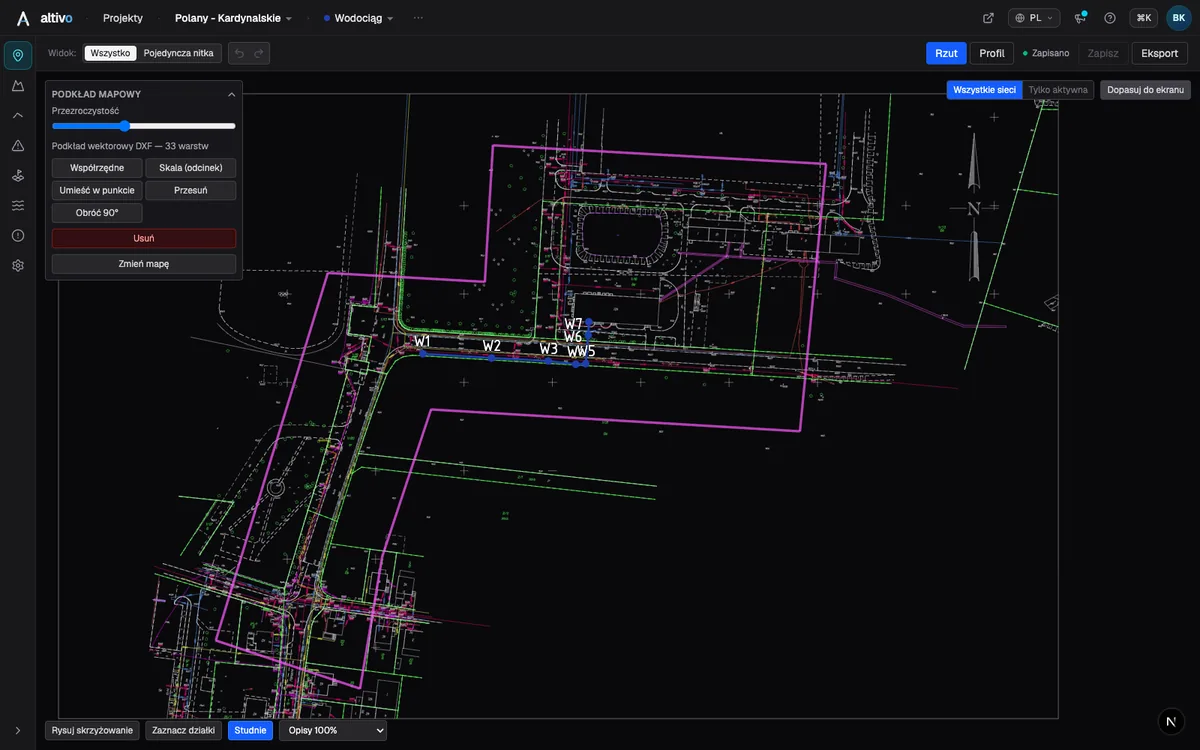
Base map as an underlay: trace your network route over DXF, PDF or PNG
How to load a survey drawing or base map as an underlay on the plan view, calibrate it to real coordinates and trace the network route over it — in the browser, without a CAD seat.
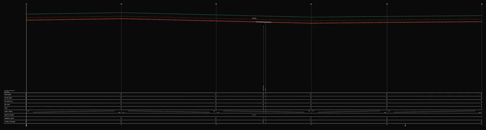
Underground cable long section — power and telecom cable routes
How to draw the longitudinal profile of a buried power or telecom cable route: minimum burial depth by voltage class, crossings, protective ducting, warning tape and a DXF export — in the browser, no CAD.
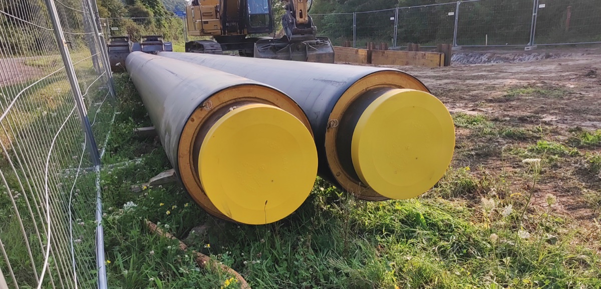
District heating long section — preinsulated pipe in profile
How to draw the longitudinal profile of a district heating network with preinsulated bonded pipe: two diameters (carrier and casing), cover to the casing crown, leak detection, crossings, the profile table and a DXF and IFC export — in the browser, no CAD.
Ready to design without the pain?
Altivo is the fastest way to produce a clean DXF. Try it today.
Start the 14-day trial