Quick answer
To turn a gravity sewer route into a deliverable DXF long section: paste X,Y,Z (or X,Y) coordinates from a survey or CAD table, set the network type to gravity sewer, then resolve invert levels, gradients (‰ or %) and cover depth reach by reach, adding drop connections where the invert steps down. Configure the profile table, then export a dual-scale DXF with clean named layers and editable MText, ready for AutoCAD, BricsCAD, ZWCAD or GstarCAD without further cleanup.
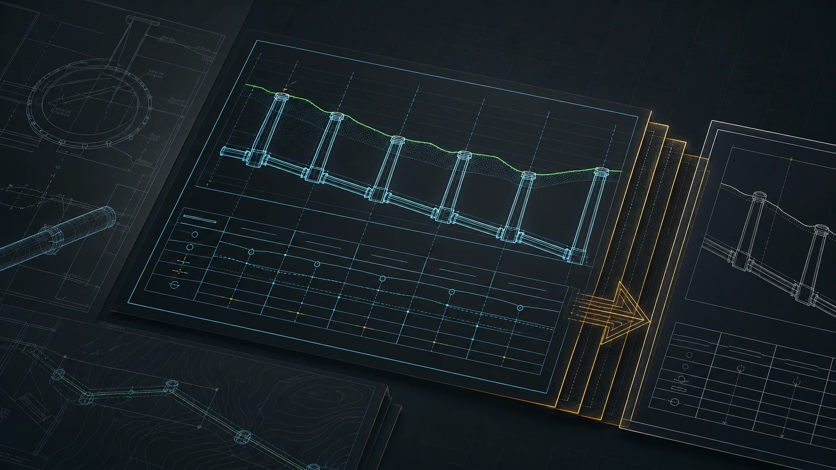
The long section of a sewer is the drawing that eats a disproportionate amount of project time for its size. The route is two days of work; the profile itself — invert levels, gradients, stationing, drop connections, annotations — can swallow another half day of fiddling in CAD and Excel. Below is a concrete path: from coordinates to a deliverable DXF, with no layer cleanup after export.
What you need as input
Coordinates of the route's characteristic points — manholes, bends, crossing locations — are enough. The format is flexible:
- X, Y, Z (existing ground level) — full variant,
- X, Y — when ground levels come from another source or you accept a default,
- any separator (comma, semicolon, tab, space) — auto-detected,
- paste from the clipboard straight out of Excel or a CAD coordinate table.
Any metric coordinate system works (UTM, national grids such as PL-2000 or OSGB36, etc.). Large coordinate values (hundreds of thousands) are automatically shifted by an offset toward zero so the drawing stays stable in CAD — no manual recalculation needed.
Step 1 — Import the route
Paste or load the points. The main run is built from consecutive points; branches attach as separate paths to a node. Set the network type to "gravity sewer" here — default depths, diameters and material become sensible immediately, and the profile is computed against the channel invert rather than the axis.
Step 2 — Levels, gradients, depths
This is the actual design work. For a gravity sewer the key quantities are:
- invert level at each manhole (derived from the gradient or entered directly),
- gradient of a reach in ‰ or % — computed automatically from levels or typed in, with the other value recalculated instantly,
- cover depth — controlled along the whole route,
- drop connection in a manhole — when the difference between inlet and outlet invert requires a step.
Minimum and maximum gradients depend on diameter and the applicable standard — see our guide on gravity sewer gradients for the design rules.
Step 3 — Objects and crossings
You place objects on the profile and plan view: manholes, chambers, road crossings, casing pipes, conflicts with other utilities. Crossings with foreign networks are marked automatically — on the plan and at the right place on the profile, with the conflict level.
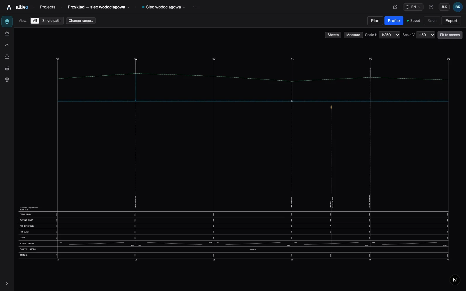
Step 4 — Profile table
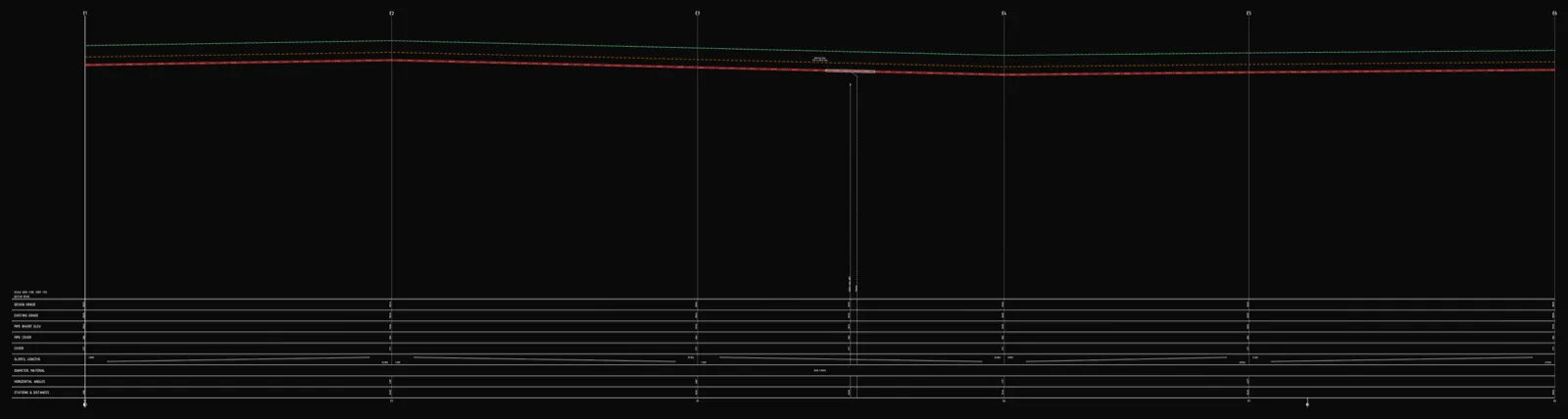
Below the drawing you configure the table rows the way your practice and reviewer require: existing and designed ground level, invert level, depth, gradients and lengths, diameter and material, stationing, angles, drop. You switch on only what belongs on the sheet. Not sure how the table is read? See how to read a long section.
Step 5 — DXF export
The most important moment — and the one where time is usually lost after a "finished" drawing. The export gives you:
- dual scale — separate horizontal and vertical (e.g. 1:500 / 1:100),
- clean, named layers — a separate layer for the ground line, pipe axis, profile table, annotations and frame,
- editable MText, not exploded geometry — fix annotations in CAD without rebuilding them,
- a correct offset, so the drawing opens where it should.
The AC1018+ file opens in AutoCAD, BricsCAD, ZWCAD or GstarCAD. The point is a DXF that is deliverable immediately, not one that needs half an hour of tidying before handover.
What you gain
What used to take hours of manual drafting and Excel recalculation becomes a few minutes and a few deliberate design decisions. No install, no dongle, in the browser — the result plugs into your existing CAD workflow without replacing anything.
Frequently asked questions
How do I export a sewer long section to DXF? Paste X,Y,Z or X,Y coordinates of the route's characteristic points from a survey or CAD table, set the network type to gravity sewer, then resolve invert levels, gradients and cover depth reach by reach, adding drop connections where the invert steps down. Configure the profile table rows your reviewer needs, then export a dual-scale DXF with clean named layers and editable MText. The file is generated in the browser and opens without further cleanup.
What coordinate formats can I import for a sewer profile? The input is flexible: X,Y,Z with the existing ground level as the full variant, or X,Y when ground levels come from elsewhere or you accept a default. Any separator — comma, semicolon, tab or space — is auto-detected, so you can paste straight from Excel or a CAD coordinate table. Any metric coordinate system works, such as UTM, PL-2000 or OSGB36; large values are automatically shifted toward zero so the drawing stays stable in CAD.
How are invert levels and gradients set on a gravity sewer? For a gravity sewer the key quantities are the invert level at each manhole, derived from the gradient or entered directly; the gradient of a reach in ‰ or %, computed automatically from levels or typed in with the other value recalculated instantly; the cover depth controlled along the whole route; and a drop connection in a manhole when the difference between inlet and outlet invert requires a step.
Why does the DXF use a dual scale with named layers? A long section uses separate horizontal and vertical scales, for example 1:500 and 1:100, so level differences stay readable over long distances. The export puts the ground line, pipe axis, profile table, annotations and frame on their own named layers, and keeps text as editable MText rather than exploded geometry. That means you can fix annotations in CAD without rebuilding them, and the file is deliverable immediately.
Try it free — 14 days, no card required.
Related articles
Underground cable long section — power and telecom cable routes
How to draw the longitudinal profile of a buried power or telecom cable route: minimum burial depth by voltage class, crossings, protective ducting, warning tape and a DXF export — in the browser, no CAD.
District heating long section — preinsulated pipe in profile
How to draw the longitudinal profile of a district heating network with preinsulated bonded pipe: two diameters (carrier and casing), cover to the casing crown, leak detection, crossings, the profile table and a DXF and IFC export — in the browser, no CAD.
Water main long section to DXF — step by step
How to draw a water main longitudinal profile: minimum cover vs frost depth, pipe centreline levels, valves and hydrants, crossings, the profile table and a clean dual-scale DXF export — in the browser, no CAD.

How to draw a pipe long section (plan & profile) without building it in Civil 3D
Generate a utility long section — plan and profile, or "profile view" in Civil 3D — straight from your data, then finish the sheet in CAD: title block, revisions, annotations. A faster split of the work, not a CAD replacement.
Ready to design without the pain?
Altivo is the fastest way to produce a clean DXF. Try it today.
Open the free app