Quick answer
In Altivo you add two kinds of elements to a long-section profile: crossings, which mark where a foreign utility (water, sewer, gas, cable) conflicts with your route, shown with a diameter and elevation; and objects, infrastructure items like manholes, valves, hydrants, roads or buildings, anchored to either a node or a segment. Both are added from the Objects and crossings panel and appear instantly on the plan, the profile and the DXF/XLSX export.
A long-section profile is rarely just the pipe. Other utilities cross the route, and manholes, roads or buildings sit along it. In Altivo you add this with two kinds of elements:
- Crossings — foreign utilities (water, sewer, gas, cables) that cross your route. They show up as a symbol at the point of conflict, with an elevation and a diameter.
- Objects — infrastructure items: manholes, chambers, roads, buildings, hydrants, valves and more. An object can be anchored either to a point (e.g. a manhole on a node) or to a segment (e.g. a road crossing the pipe).
Here is the whole workflow, step by step.
1. Open the “Objects and crossings” panel
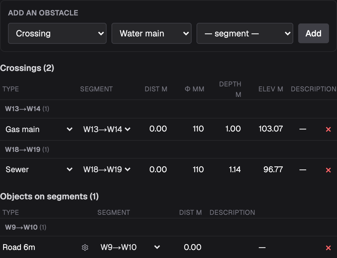
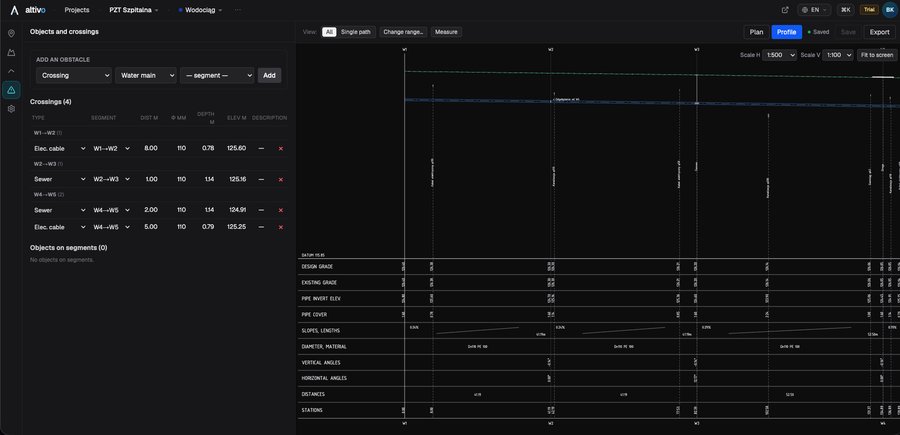
In the mode rail on the left, click the Objects and crossings icon (keyboard shortcut 4). The panel shows the Add an obstacle form and two lists: Crossings and Objects on segments.
2. Add a crossing
In the Add an obstacle form, do three things:
- In the first dropdown choose Crossing.
- Pick the utility: Water main, Sewer, Gas main, Heating pipe, Electric cable or Telecom cable.
- Choose the segment where the conflict sits and click Add.

The crossing appears in the Crossings list, grouped by segment, with a default diameter and an elevation computed for that utility.
3. Edit a crossing
Every field is edited in place — just click the cell and type:
- Dist m — distance from the start of the segment,
- φ mm — diameter of the foreign pipe,
- Depth m — cover depth,
- Elev m — elevation of the crossing axis,
- Description — any note.
The dropdowns also let you change the utility and the segment, and the red × deletes the crossing.
Depth m and Elev m are linked: entering the axis elevation recomputes the depth relative to the ground, and vice versa. Provide just one of them — Altivo derives the other.
4. Add an object on a segment
In the same form, choose Object on segment in the first dropdown. The second dropdown turns into an object type picker:
Manhole, Chamber, Building, Hydrant, Valve, Drain, Road, Fence, Pole / light, Pump station, Separator / settling tank, Casing pipe, Air valve, Gas cabinet, Curb.
Pick the type, choose a segment and click Add.

5. Set the object’s parameters
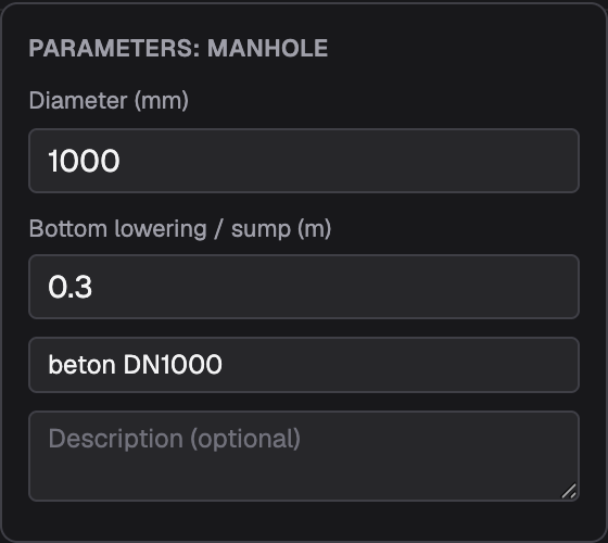
Each object has its own set of parameters. Click the gear icon (“Edit parameters”) next to the object — a Parameters: … popover opens with fields that depend on the type (for a road: width; for a manhole: diameter and bottom lowering). The Material / class and Description fields are optional.
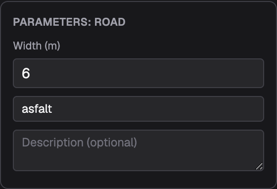
Changes are saved live — what you type goes straight into the drawing. There is no separate
“Save” button inside the popover; close it with Esc or by clicking outside.
6. Objects on a point (e.g. a manhole on a node)
Manholes, chambers and hydrants are usually anchored to a point on the route. Switch to the Points mode (shortcut 1) and, in the Type column of the chosen node, click — and pick the object type. A gear icon appears next to the name to edit its parameters.
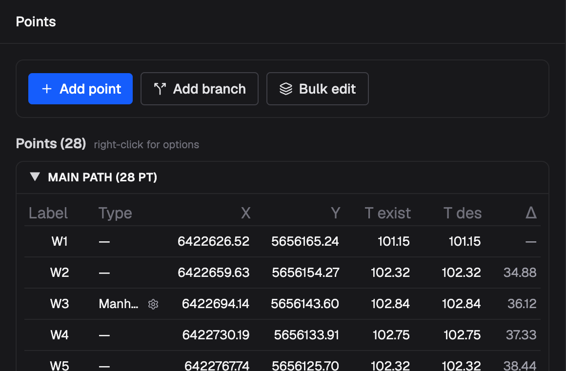
The parameters popover works just like it does for objects on a segment:
7. The result on the profile
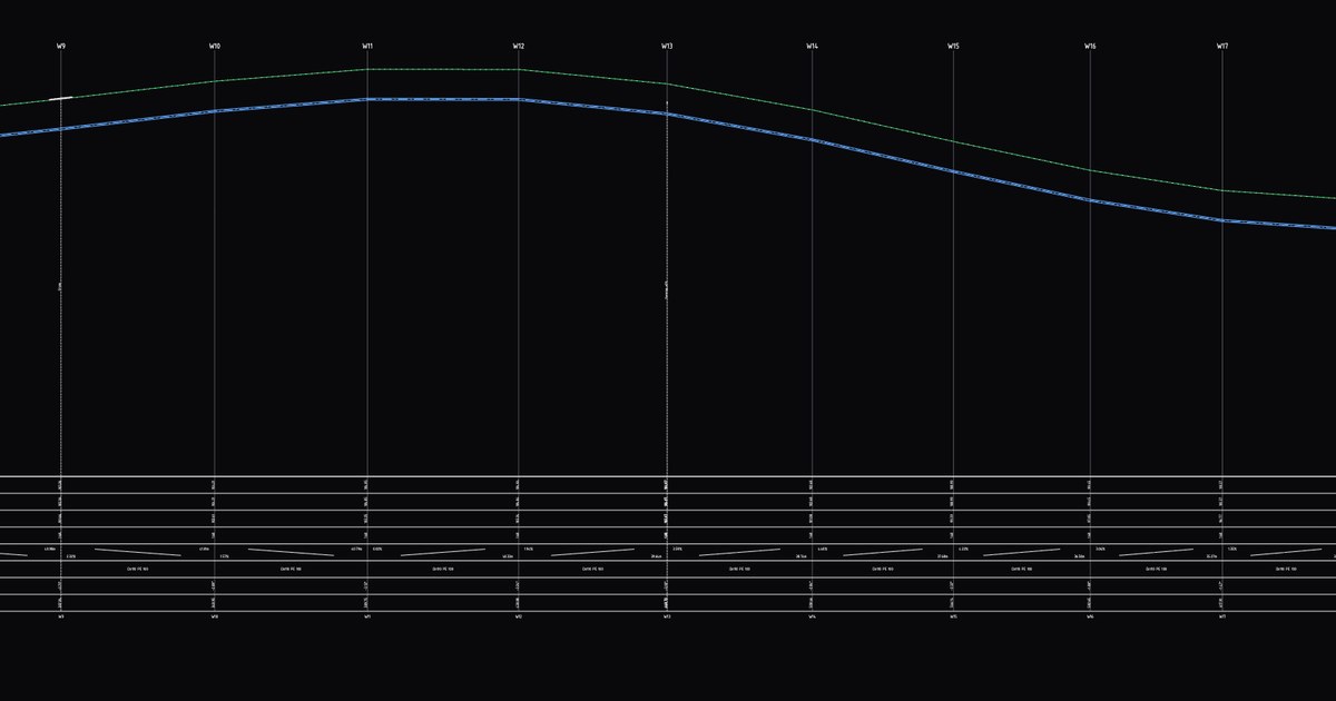
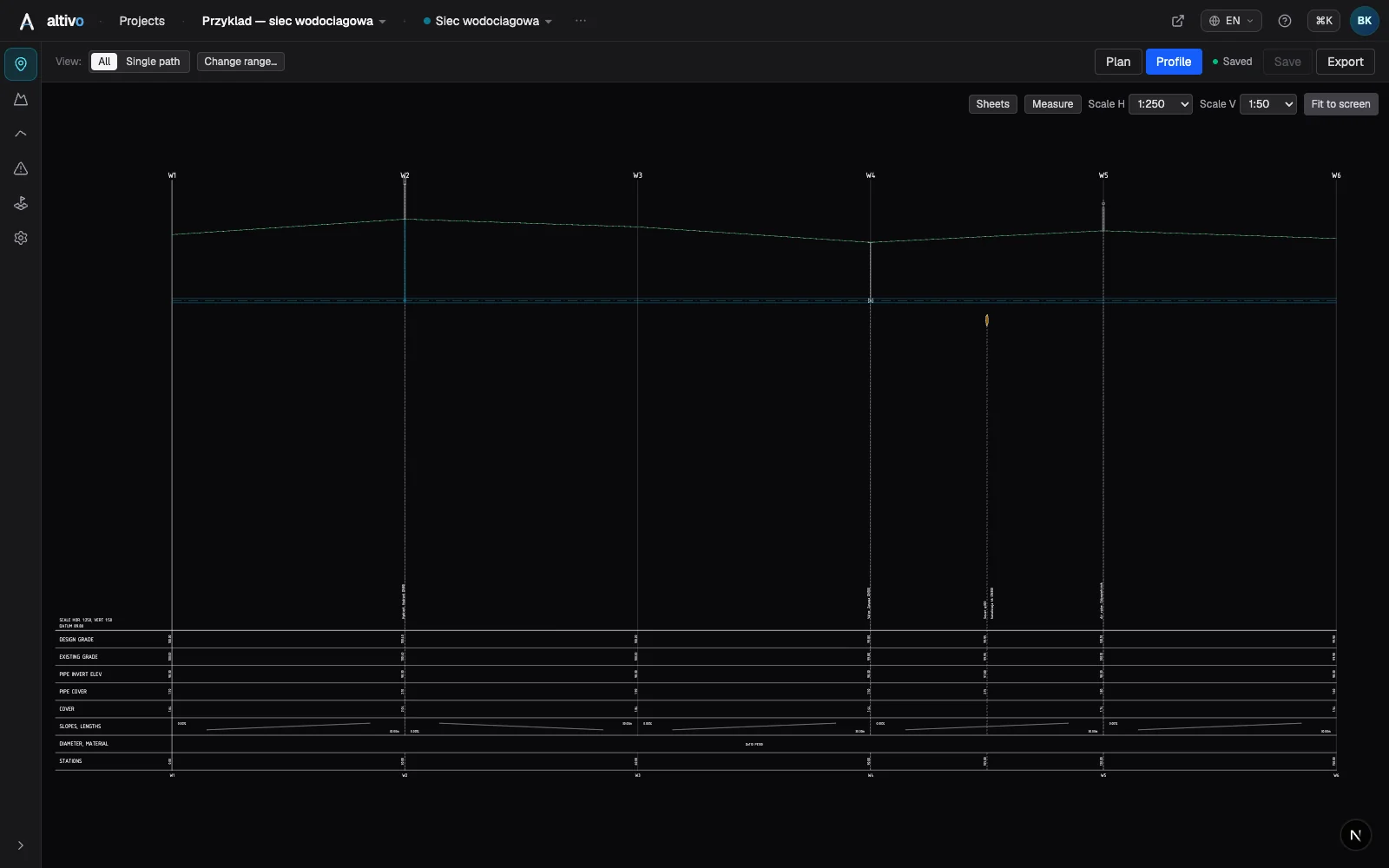
Crossings and objects show up immediately on the long-section profile — together with the stationing, elevations and the data table ready for DXF export.
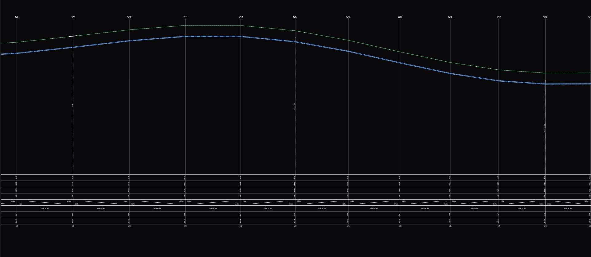
Crossings and objects are also included in the DXF/XLSX export — symbols are drawn to scale and the descriptions and elevations are written into the data table. So get the elevations right while you place the conflicts.
Frequently asked questions
How do I add a utility crossing on a long-section profile? In Altivo, open the Objects and crossings panel from the mode rail on the left, or press the 4 shortcut. In the Add an obstacle form choose Crossing, pick the foreign utility (water main, sewer, gas main, heating pipe, electric or telecom cable) and the segment where the conflict sits, then click Add. The crossing appears in the list and on the plan and profile with a default diameter and a computed elevation.
What objects can I place on a utility profile? You can anchor infrastructure items to a point or a segment: manhole, chamber, building, hydrant, valve, drain, road, fence, pole or light, pump station, separator or settling tank, casing pipe, air valve, gas cabinet and curb. Each has its own parameters, for example width for a road, or diameter and bottom lowering for a manhole, edited from its Parameters popover.
How do I edit a crossing's depth and elevation? Every field is edited in place — click the cell and type. You can set the distance from the start of the segment, the foreign pipe diameter, the cover depth, the axis elevation and a description. Depth and elevation are linked: enter the axis elevation and Altivo recomputes the depth relative to the ground, or enter the depth and it derives the elevation. Provide just one of the two.
Do crossings and objects appear in the DXF export? Yes. Crossings and objects show up immediately on the long-section profile with stationing, elevations and the data table, and they are included in the DXF and XLSX export. Symbols are drawn to scale and the descriptions and elevations are written into the data table, so it's worth getting the elevations right while you place the conflicts.
Related articles
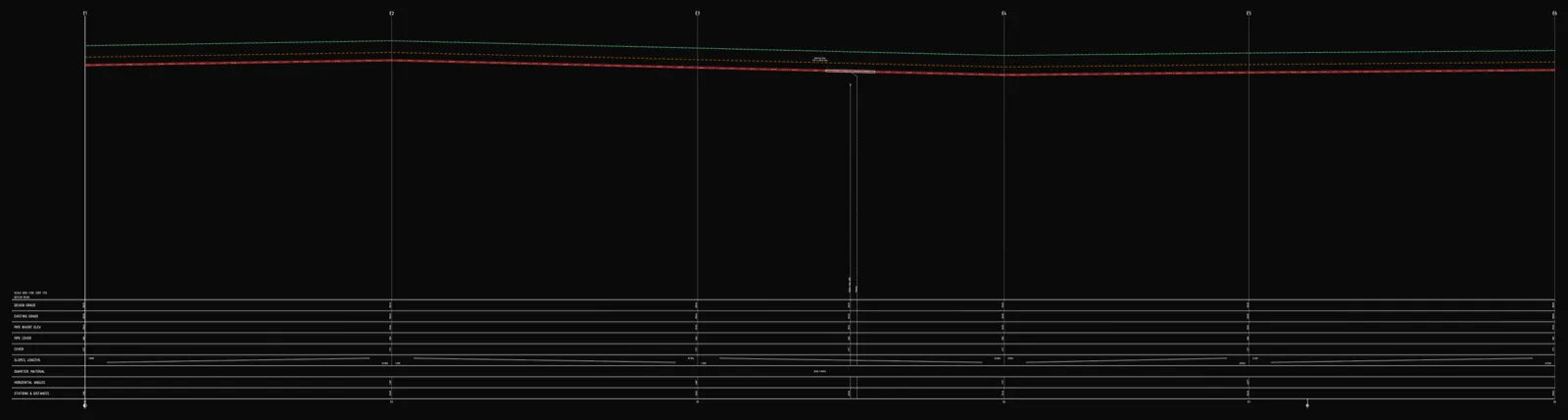
Underground cable long section — power and telecom cable routes
How to draw the longitudinal profile of a buried power or telecom cable route: minimum burial depth by voltage class, crossings, protective ducting, warning tape and a DXF export — in the browser, no CAD.
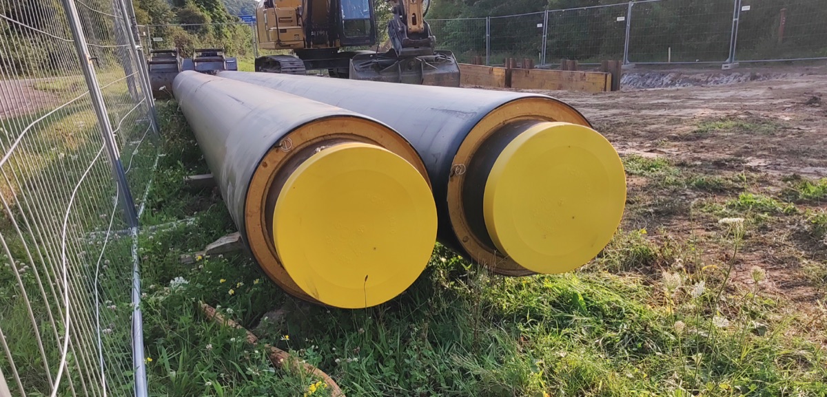
District heating long section — preinsulated pipe in profile
How to draw the longitudinal profile of a district heating network with preinsulated bonded pipe: two diameters (carrier and casing), cover to the casing crown, leak detection, crossings, the profile table and a DXF and IFC export — in the browser, no CAD.
Water main long section to DXF — step by step
How to draw a water main longitudinal profile: minimum cover vs frost depth, pipe centreline levels, valves and hydrants, crossings, the profile table and a clean dual-scale DXF export — in the browser, no CAD.
How to read a utility long section (longitudinal profile)
A practical guide to the long section of a water, sewer or gas network: ground line, pipe invert, gradients, stationing, the profile table and what a reviewer checks.
Ready to design without the pain?
Altivo is the fastest way to produce a clean DXF. Try it today.
Start the 14-day trial