Quick answer
A water main long section is driven by minimum cover, not gradient — there's no invert to design against. Under BS EN 805 and UK practice, typical minimum cover is 750 mm in verges and 900 mm under carriageways, keeping the crown below the local frost line; colder climates can need 1.0–1.8 m or more. The profile also carries valves, hydrants, air valves and crossings, then exports as a dual-scale DXF ready for CAD.
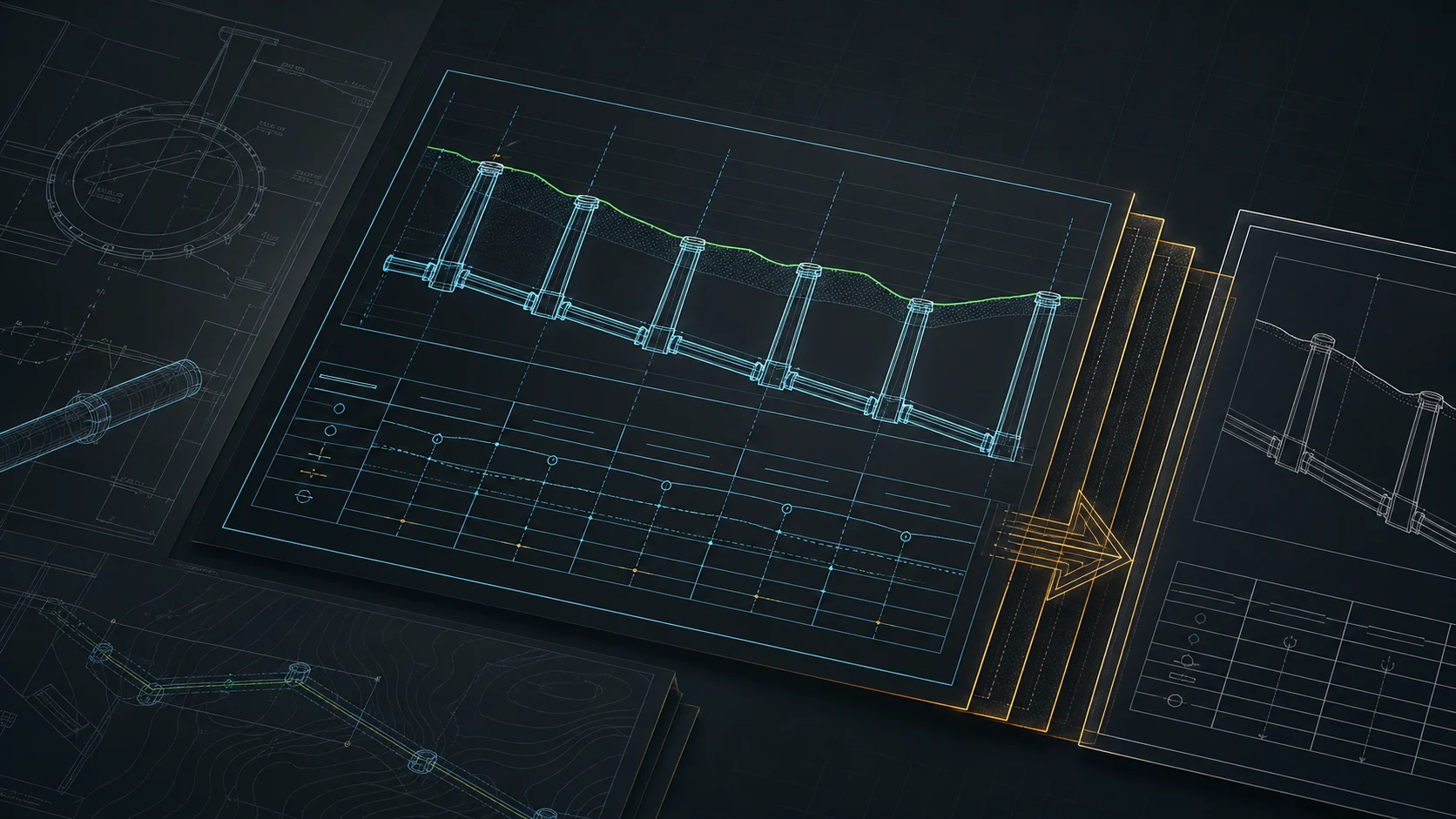
A water main long section is drawn differently from a gravity sewer — and it isn't simpler. There's no gravity gradient setting the invert, so the pipe depth isn't a by-product of slope. Three things drive it instead: minimum cover (frost protection), node fittings (valves, hydrants, air valves) and crossings with other utilities. That changes the order you work in. Below is a concrete path from coordinates to a deliverable DXF.
How a water main profile differs from a sewer
In a gravity sewer the invert level follows the gradient — you design the slope and depth is the consequence. A water main is the opposite: the pipe can run almost level or follow the ground, and its depth is set by minimum cover over the pipe crown, keeping the main below the local frost line. Longitudinal slopes on a water main are designed mainly for air release and drainage (rises to air valves, low points to washouts), not for flow. So you read the profile from the cover, not the gradient.
What a water main profile must contain
A checklist for approval:
- alignment with chainage and existing + proposed ground levels,
- centreline (or crown) level of the pipe at nodes,
- minimum cover controlled along the whole length,
- valves, hydrants, air valves, nodes with fittings,
- crossings with other utilities and the crossing level,
- protective sleeves under roads and at crossings,
- pipe diameter, material and run lengths.
Minimum cover — what governs depth
For a buried water main, depth is governed by cover, and cover is governed mainly by frost. Under BS EN 805 and UK water-industry practice, typical minimum cover is 750 mm in verges and footways and 900 mm under carriageways, with a usual maximum around 1350 mm. In colder climates the rule is simpler to state and harder to meet: the pipe crown must sit below the local frost line, which in northern US states or continental Europe can mean 1.0–1.8 m or more. Shallower laying is allowed only with insulation and justification.
| Context | Typical minimum cover |
|---|---|
| Verges / footways (BS EN 805, UK) | 750 mm |
| Under carriageways | 900 mm |
| Below frost line (cold climates) | 1.0–1.8 m+ |
Whatever the figure, the point on the profile is the same: keep the crown below it everywhere.
Step by step in Altivo
1. Points with chainage. Paste node coordinates (X, Y, optional Z) straight from a spreadsheet or a CAD coordinate table; separators are detected automatically and large coordinates are offset toward zero. Set the network kind to water so the profile is computed against the pipe centreline and defaults (PE, PVC) make sense.
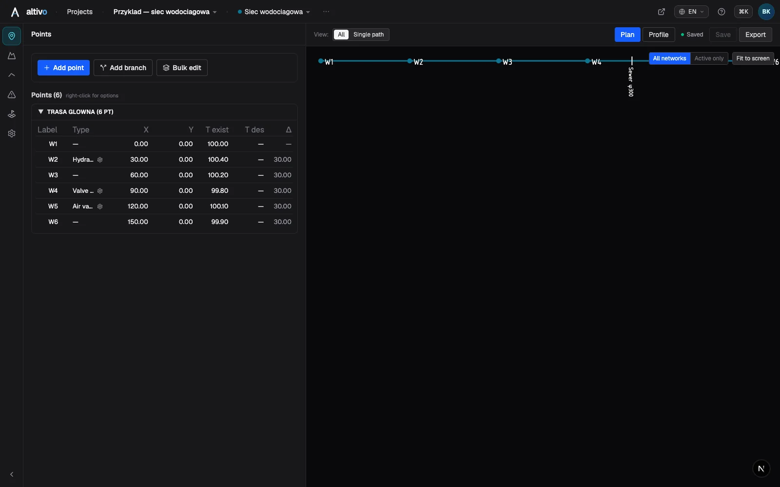
2. Ground levels. Fill in existing ground elevation at nodes, plus extra terrain points between nodes where the ground undulates — these decide how deep you must go to hold cover.
3. Depth / centreline. Set the depth or centreline level so the cover over the crown never drops below your minimum. Cover is checked along the whole run, so you immediately see where the pipe rises too shallow.
4. Objects — fittings. From the object library you place hydrants, valves, air valves and nodes. Each anchors to a node or a segment and shows on both the plan and the profile.
5. Crossings. Clashes with foreign utilities (cables, gas, sewer) are marked as crossings — they appear automatically on the plan and in the profile with the crossing level. Add a protective sleeve under roads and at clashes.
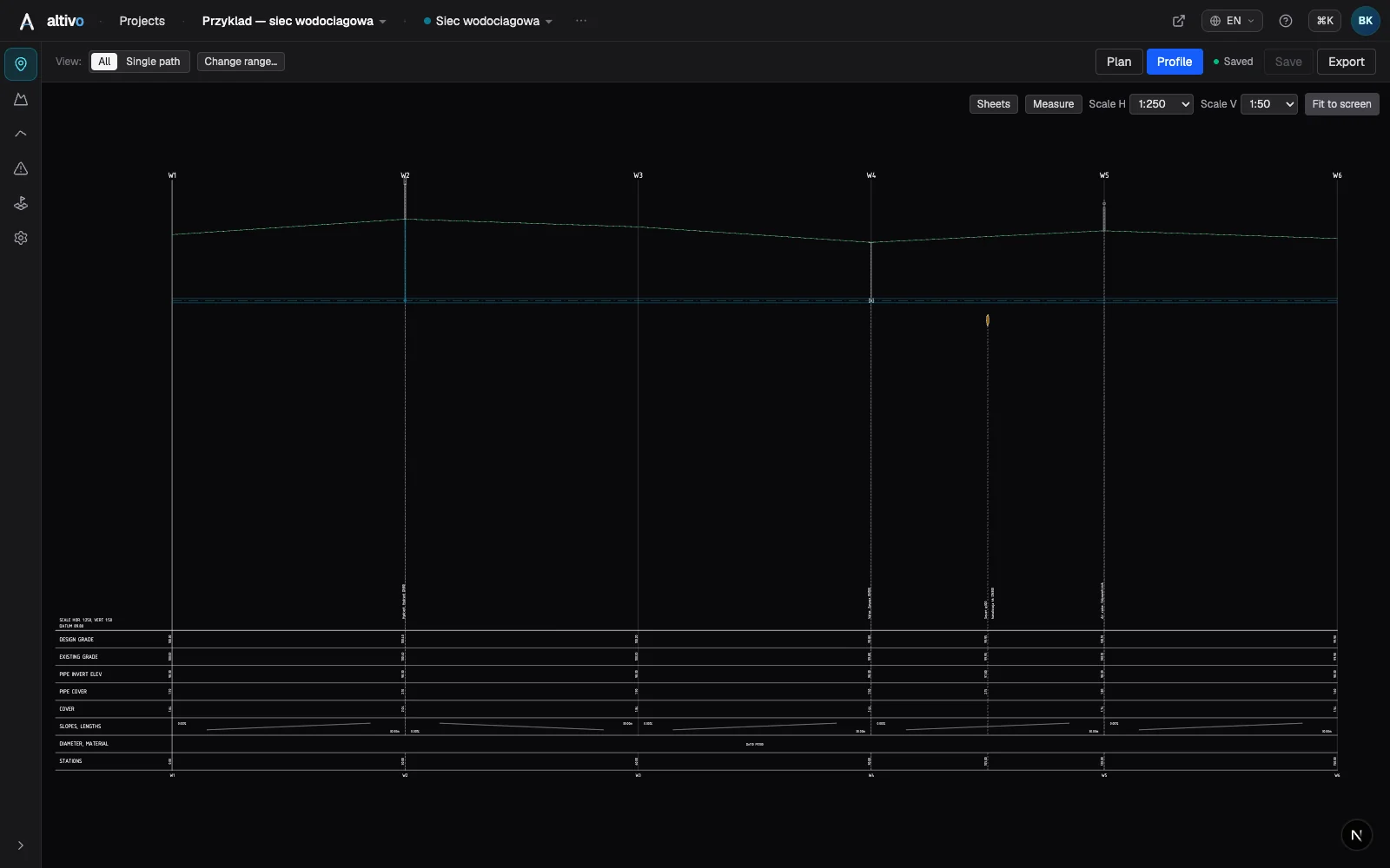
6. Profile table. Configure the rows your reviewer expects: existing and proposed ground level, pipe centreline level, cover, lengths and chainage, diameter and material. Switch on only what belongs on the drawing.
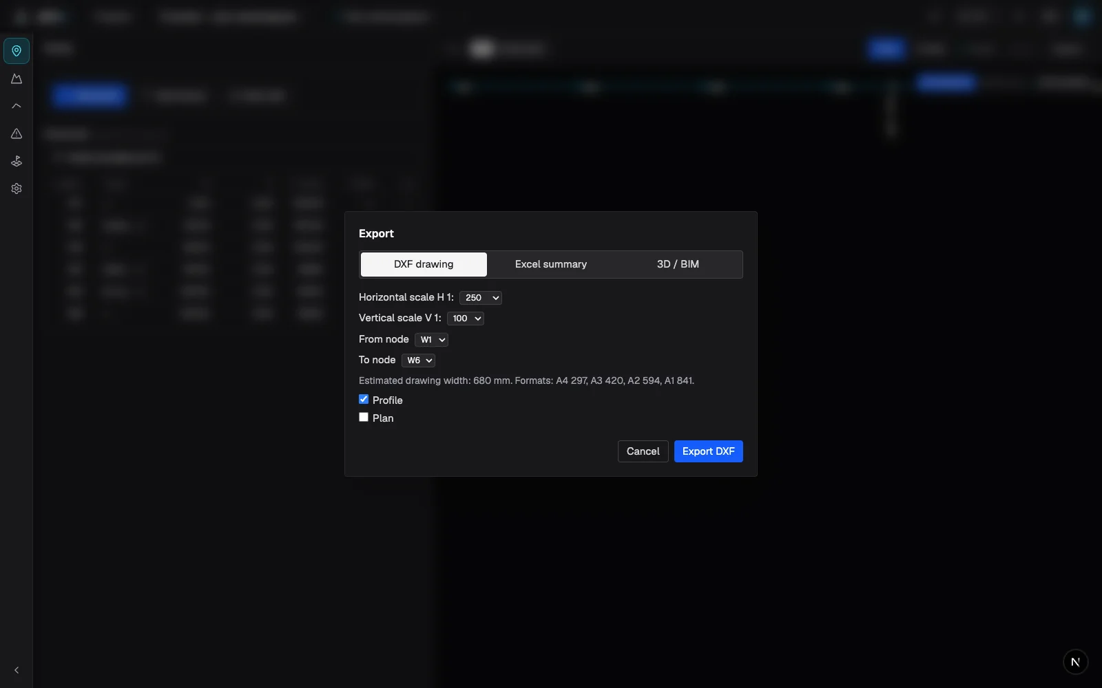
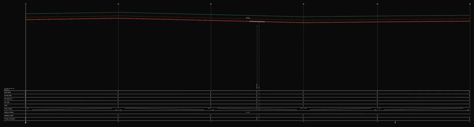
7. DXF export. A file with dual scale (horizontal and vertical set independently, e.g. 1:500 / 1:100), clean named layers and editable MText — deliverable as-is, no layer cleanup. Opens in AutoCAD, BricsCAD, ZWCAD or GstarCAD.
FAQ
What's the minimum depth for a water main? Enough for the pipe crown to sit below the local frost line, or to meet the cover figure in your standard (e.g. 750 mm in verges, 900 mm under carriageways per BS EN 805). Shallower only with insulation.
Is a service connection profile drawn the same way? In principle yes — a service is a shorter run from the main to the building, governed by the same cover. It's the subject of a separate, shorter guide.
What scale should I use? Typically 1:100 vertical and 1:500 or 1:1000 horizontal — the dual scale is set independently in the DXF export.
What you gain
A water main profile that takes half a day by hand in CAD and a spreadsheet becomes a few deliberate design decisions and minutes. No install, in the browser — the result plugs into your existing CAD workflow without replacing it.
See also: Sewer long section to DXF step by step, How to add crossings and objects.
Try it free — 14 days, no card required.
Related articles
Underground cable long section — power and telecom cable routes
How to draw the longitudinal profile of a buried power or telecom cable route: minimum burial depth by voltage class, crossings, protective ducting, warning tape and a DXF export — in the browser, no CAD.
District heating long section — preinsulated pipe in profile
How to draw the longitudinal profile of a district heating network with preinsulated bonded pipe: two diameters (carrier and casing), cover to the casing crown, leak detection, crossings, the profile table and a DXF and IFC export — in the browser, no CAD.
Sewer long section to DXF — step by step
From field coordinates to a CAD-ready longitudinal profile of a gravity sewer. A concrete walkthrough: import, gradients, manholes, drop connections, dual-scale DXF export.

How to draw a pipe long section (plan & profile) without building it in Civil 3D
Generate a utility long section — plan and profile, or "profile view" in Civil 3D — straight from your data, then finish the sheet in CAD: title block, revisions, annotations. A faster split of the work, not a CAD replacement.
Ready to design without the pain?
Altivo is the fastest way to produce a clean DXF. Try it today.
Open the free app