Quick answer
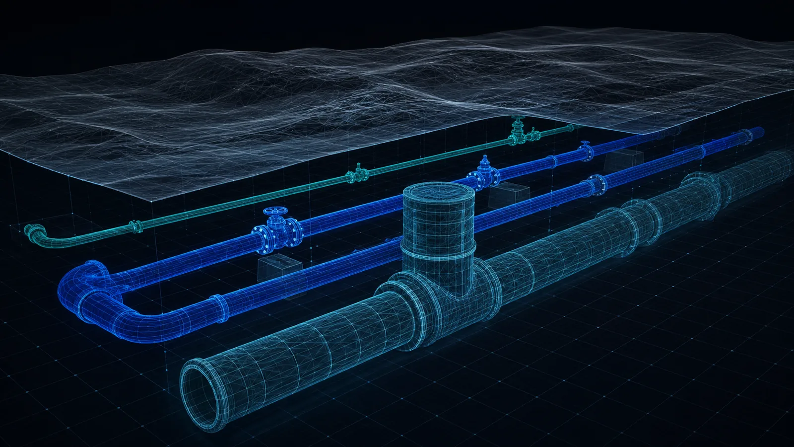
IFC (Industry Foundation Classes, ISO 16739) is the open, vendor-neutral BIM exchange format: instead of drawing geometry like DXF, it carries objects with meaning, a pipe becomes an IfcPipeSegment, a valve an IfcValve, a hydrant an IfcFireSuppressionTerminal, openable in any IFC-compliant viewer or in Revit, ArchiCAD or Civil 3D. Altivo exports a designed utility network as a georeferenced IFC 4 model, plus a 3D DXF, directly from the browser.
More and more projects — especially large and publicly funded ones — require handing over not just drawings but a 3D model. Building disciplines have worked in BIM for years; buried utilities are catching up faster than most people expect. The common language of that exchange is the IFC format. Altivo exports your designed network straight to IFC and to 3D DXF — this article explains what the format is and how to use it.
What is IFC?
IFC (Industry Foundation Classes) is an open, vendor-neutral format for BIM models, developed by buildingSMART and standardised as ISO 16739. The simplest way to think about it is "PDF for BIM models": no matter which tool the design was made in — Revit, ArchiCAD, Allplan, Civil 3D — a model saved as IFC opens in any software that supports the standard. In the UK it sits at the heart of the ISO 19650 / openBIM workflow required on most public-sector projects.
Unlike DXF, which carries drawing geometry (lines, text, layers), IFC carries objects with meaning: a pipe is an IfcPipeSegment with a material and diameter, a valve is an IfcValve, a hydrant is an IfcFireSuppressionTerminal. The receiving application doesn't see "lines" — it sees network elements it can filter, schedule and clash-check.
Why would a utility designer need IFC?
- Multi-discipline coordination. The lead designer or contractor federates models from every discipline and finds clashes before they appear on site. A network delivered as IFC simply drops into the federated model in the right place.
- Client requirements. Public-sector frameworks in the UK, Germany and Scandinavia increasingly mandate IFC deliverables, and large infrastructure clients elsewhere are following.
- Review and handover. An IFC model opens in free viewers (e.g. BIMvision or openIFCviewer) — the reviewer needs no licence to inspect the network in 3D with real levels.
What exactly Altivo exports
Altivo's 3D export generates an IFC 4 file — a reference model of the network:
- pipe runs as elements with their real diameters, following the designed levels — for gravity sewers, the invert levels you set — in full grid coordinates,
- network fittings mapped to the proper IFC classes, including:
| Object in Altivo | IFC class |
|---|---|
| valve, air valve | IfcValve |
| hydrant | IfcFireSuppressionTerminal |
| road gully | IfcWasteTerminal |
| separator | IfcInterceptor |
| casing pipe | IfcPipeSegment (ObjectType “CASING”) |
| cable duct | IfcCableCarrierSegment |
- manually added crossings with existing utilities — exported as short runs perpendicular to the route, with the entered diameter and axis level, so clashes with existing infrastructure show up in the coordination model.
You can export several networks at once — each discipline lands in the model separately, with its own objects.
Georeferencing: the model lands in the right place
The biggest trap in any 3D export is positioning the model in space. Altivo handles it explicitly:
- at export you pick the coordinate reference system (EPSG code) — e.g. British National Grid (EPSG:27700) or any metric projected system; the CRS label is written into the IFC in a way BIM software reads machine-wise,
- you choose the E/N axis mapping. In some survey conventions the X axis means northing — misreading it shifts the model by hundreds of kilometres, so Altivo previews the resulting coordinates before export,
- the export offset is additionally stored in an
Altivo_Georeferenceproperty set, so the source coordinates can always be reconstructed.
In Revit you load the file via "Link IFC" (georeferencing is fully supported from Revit 2026). One honest caveat: this is a reference model for coordination — not native, editable Revit pipework.
3D DXF — for those staying in CAD
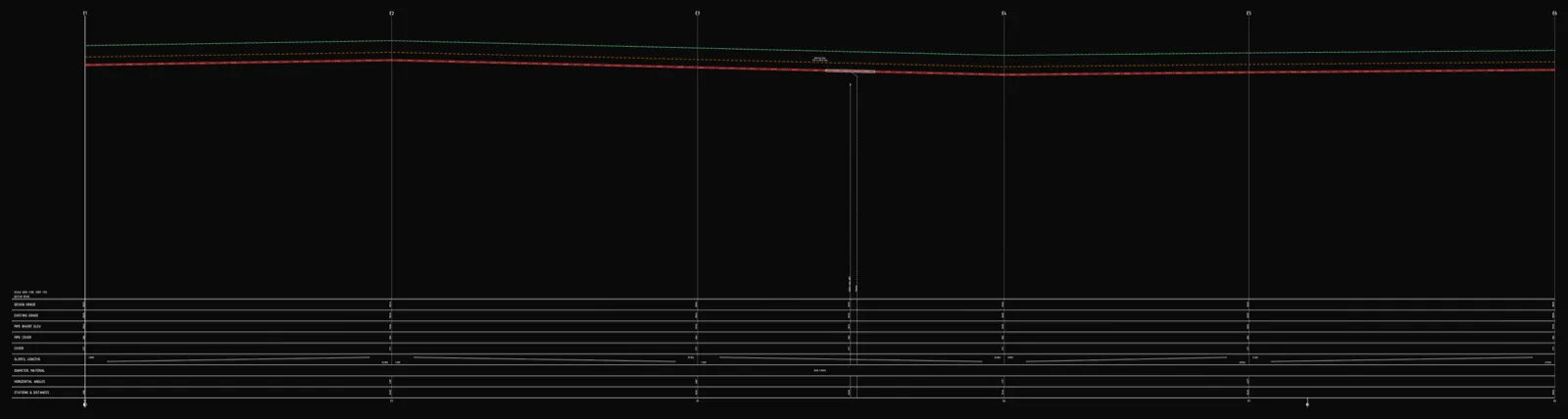
Not every recipient works in BIM. That's why, alongside IFC, Altivo also exports a 3D DXF: pipe axes as 3D lines plus simplified solids sized by diameter, in full E/N coordinates. It's a ready-made elevation underlay for AutoCAD or Civil 3D — no BIM objects, but the true geometry of the network in space. If you've been drawing pipe long sections without Civil 3D, this is the missing 3D piece.
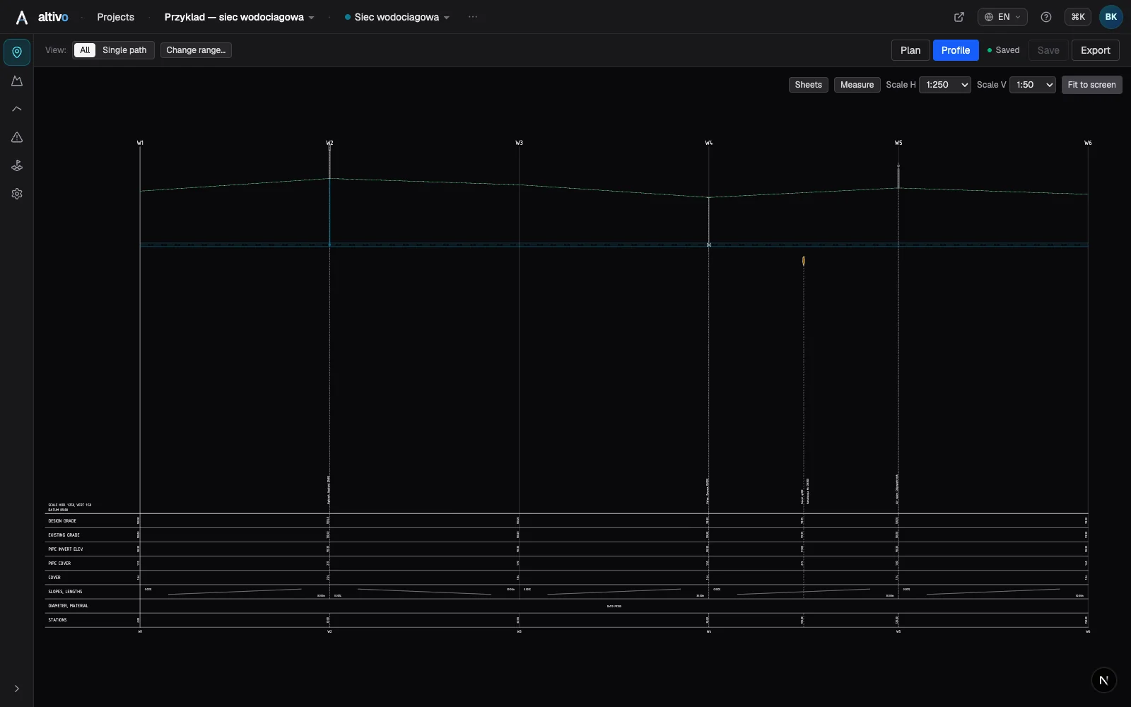
How to do it in Altivo — step by step
- Open your project and click Export, then the "3D / BIM" tab.
- Tick the formats: IFC, 3D DXF or both.
- Pick the coordinate system (EPSG) and verify the E/N axis mapping in the preview.
- Select the networks to include and click Export 3D.
Two technical prerequisites: the network must be entered in coordinate mode (not schematically, by distances only) and have ground levels filled in. If anything is missing, the export dialog tells you exactly which network and which point.
The full design workflow — from importing coordinates to the classic flat profile DXF — is covered in sewer long section to DXF, step by step.
Frequently asked questions
What is IFC in BIM? IFC (Industry Foundation Classes) is an open, vendor-neutral format for BIM models, developed by buildingSMART and standardised as ISO 16739. Think of it as PDF for BIM models: whatever tool a design was made in, a model saved as IFC opens in any software that supports the standard. Unlike DXF, which carries drawing geometry, IFC carries objects with meaning that the receiving application can filter, schedule and clash-check.
Why would a utility designer need IFC? IFC matters for multi-discipline coordination, because a network delivered as IFC drops into the federated model in the right place so clashes are found before site. Public-sector frameworks in the UK, Germany and Scandinavia increasingly mandate IFC deliverables. And an IFC model opens in free viewers like BIMvision, so a reviewer needs no licence to inspect the network in 3D with real levels.
What does Altivo export as IFC? Altivo's 3D export generates an IFC 4 reference model of the network: pipe runs with their real diameters following the designed levels in full grid coordinates, network fittings mapped to the proper IFC classes such as IfcValve for valves and IfcFireSuppressionTerminal for hydrants, and manually added crossings with existing utilities as short perpendicular runs. You can export several networks at once, each discipline landing separately with its own objects.
How does Altivo georeference the IFC model? At export you pick the coordinate reference system by EPSG code, for example British National Grid (EPSG:27700), and the CRS label is written into the IFC so BIM software reads it machine-wise. You also choose the E and N axis mapping, and Altivo previews the resulting coordinates before export so you don't shift the model by hundreds of kilometres. The offset is stored in an Altivo_Georeference property set so source coordinates can be reconstructed.
Summary
IFC is currently the safest way to hand a utility design over to the BIM world: an open standard, readable by every tool, with objects instead of lines. In Altivo, the same project you generate the long section and 2D DXF from also exports — in one click — as a georeferenced IFC model and a 3D DXF underlay.
Try Altivo for free — in the browser, no install, 14 days without a card.
Related articles
Underground cable long section — power and telecom cable routes
How to draw the longitudinal profile of a buried power or telecom cable route: minimum burial depth by voltage class, crossings, protective ducting, warning tape and a DXF export — in the browser, no CAD.
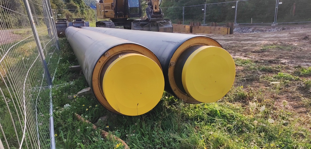
District heating long section — preinsulated pipe in profile
How to draw the longitudinal profile of a district heating network with preinsulated bonded pipe: two diameters (carrier and casing), cover to the casing crown, leak detection, crossings, the profile table and a DXF and IFC export — in the browser, no CAD.
Water main long section to DXF — step by step
How to draw a water main longitudinal profile: minimum cover vs frost depth, pipe centreline levels, valves and hydrants, crossings, the profile table and a clean dual-scale DXF export — in the browser, no CAD.

How to draw a pipe long section (plan & profile) without building it in Civil 3D
Generate a utility long section — plan and profile, or "profile view" in Civil 3D — straight from your data, then finish the sheet in CAD: title block, revisions, annotations. A faster split of the work, not a CAD replacement.
Ready to design without the pain?
Altivo is the fastest way to produce a clean DXF. Try it today.
Open the free app