How to draw a pipe long section (plan & profile) without building it in Civil 3D

Quick answer
You can generate a pipe long section, called plan and profile in North America and profile view in Civil 3D, without building a surface, alignment and pipe network there. Paste route coordinates, set levels and gradients, add objects and crossings, then export a dual-scale DXF with named layers and editable MText that opens directly in AutoCAD, BricsCAD, ZWCAD, GstarCAD or AutoCAD LT. You still finish the sheet, title block, revisions, annotations, in CAD.
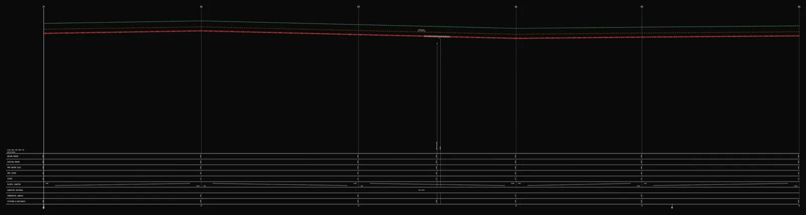
The same drawing has three names depending on who you ask. UK and Australian engineers call it a long section (longitudinal section). North American utility sets call it the plan and profile. In AutoCAD Civil 3D it is the profile view. It is the same deliverable: one view down the axis of a pipe run showing the ground line, the pipe invert, gradients, depths, stationing and the profile table below.
It is also the part of the job that eats time out of all proportion to its size. The route can be a couple of days of survey and design. Turning that into a clean, reviewable profile — and keeping the table, labels and geometry in agreement through every revision — can swallow another half-day inside CAD.
This article is about splitting that work differently. Not about abandoning your CAD environment: the profile ends up there anyway, because that is where you add the title block, drawing frame, project notes, revisions and where you combine it with the rest of the sheet set. The question is only where the profile gets built — point by point in Civil 3D, or generated from your data and handed to CAD already drawn.
Why the profile is the slow part in Civil 3D
Drawing a pipe profile in Civil 3D is not one step. To get a profile view on the sheet you typically need to:
- Build or import a surface for existing ground,
- Create an alignment along the pipe run,
- Sample a surface profile along that alignment,
- Build a pipe network (or pressure network) with the right parts list,
- Create a profile view and draw the network into it,
- Configure band sets, styles and label styles so the invert levels, depths, gradients and stationing actually show up the way your reviewer expects.
Each of those is configurable, powerful and — for a single short run or a service connection — heavy. The Autodesk tutorials and the "7 steps to a pipeline profile" walkthroughs exist precisely because the path has that many moving parts. For a large highway-drainage model that overhead pays off. For a 12-manhole gravity sewer or a water service connection, most of the time goes into setup and styling, not into design decisions.
If you want the design rules behind those decisions rather than the drafting, see our guide on how to read a long section and on gravity sewer gradients.
The faster split: generate the profile, finish it in CAD
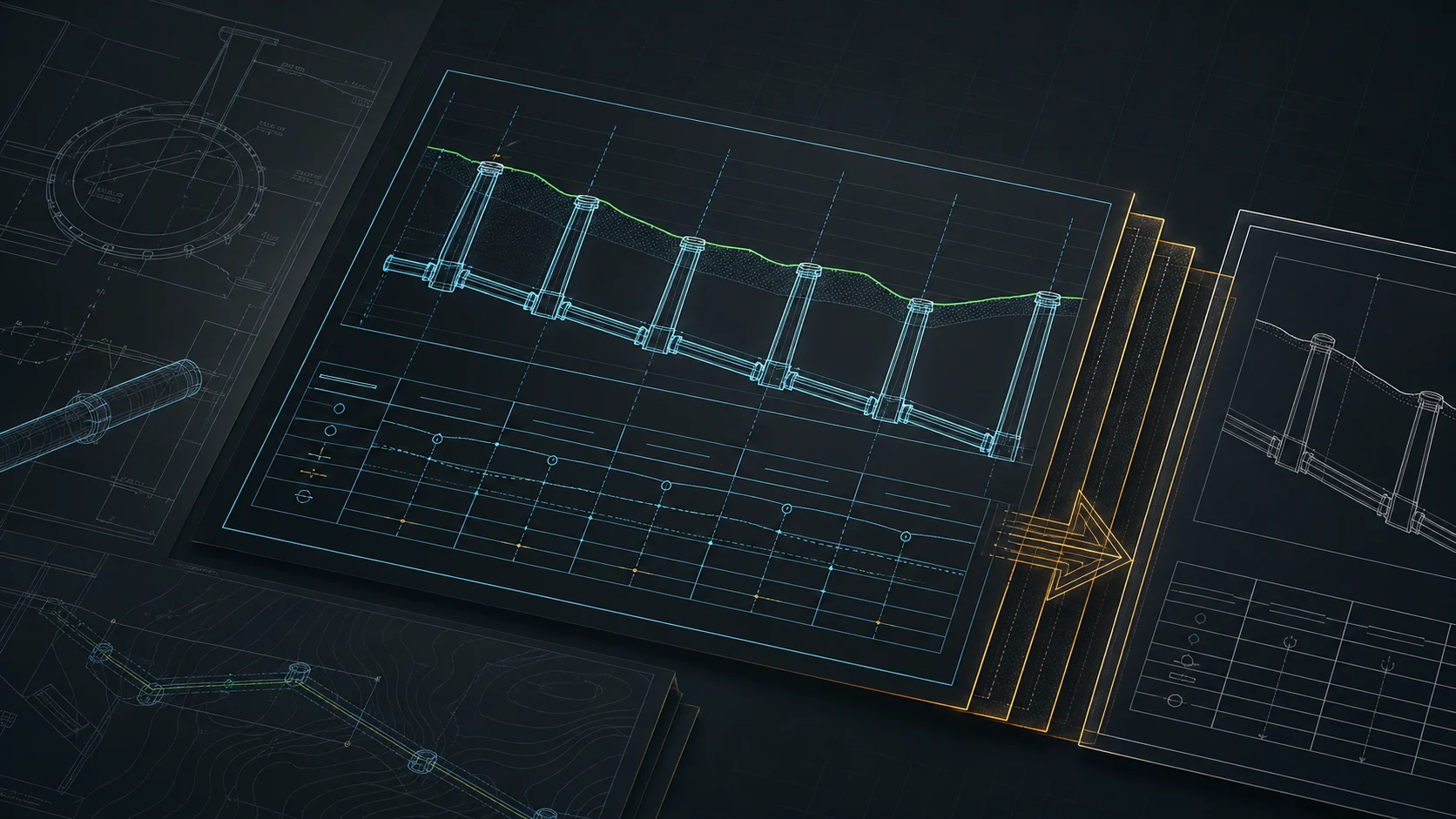
The alternative is to treat the profile as a generated artefact. You give a focused tool the data it needs, it computes the dependent values and draws the longitudinal profile to scale, and it exports a DXF that opens directly in your CAD. You then do in CAD only what CAD is actually for: framing and finishing the drawing.
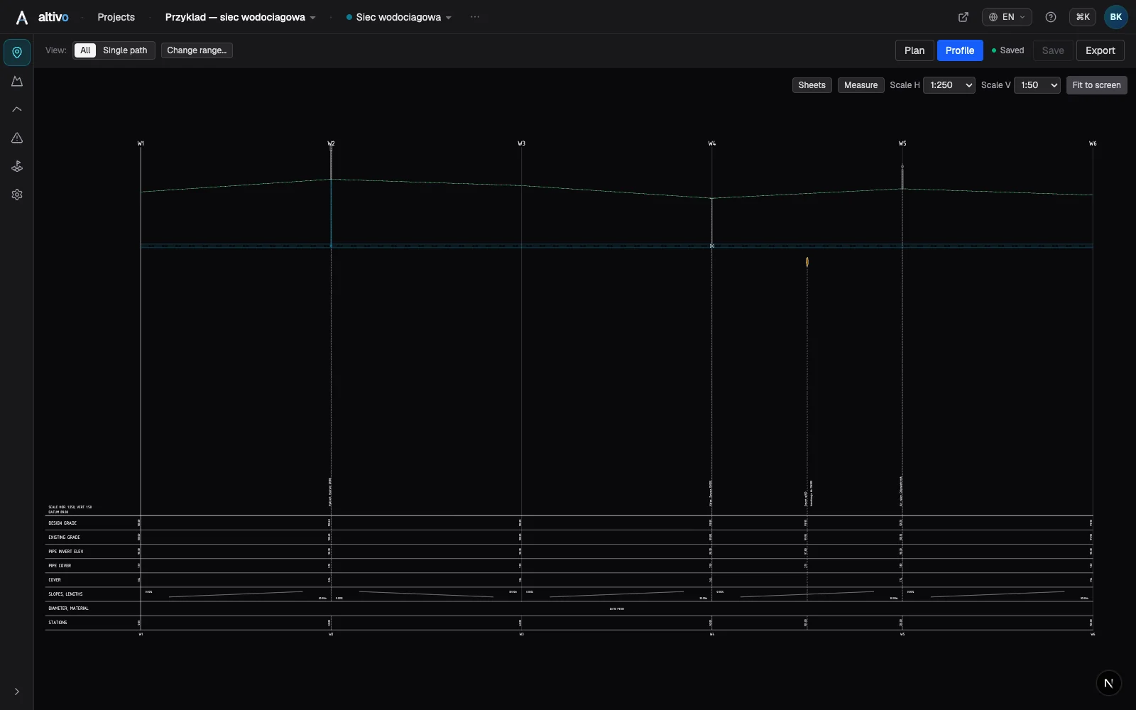
Here is the concrete path in Altivo.
Step 1 — Paste the route
Coordinates of the characteristic points — manholes, bends, crossing locations — are enough. X, Y, Z gives you ground levels too; X, Y works when levels come from elsewhere. Any separator is auto-detected, so you can paste straight from Excel or a CAD coordinate table. Any metric system works (UTM, OSGB36, national grids); large coordinate values are shifted toward zero automatically so the drawing stays stable in CAD.
Step 2 — Levels, gradients, depths
This is the part that is genuinely design, and the only part worth your attention. Enter invert levels or let them follow a gradient; type a gradient in ‰ or % and the levels recompute, or vice versa. Ground and invert elevations drive the cover depth, which is tracked along the whole route, and a drop connection appears in a manhole when the inlet/outlet invert difference calls for one.
Step 3 — Objects and crossings
Manholes, chambers, road crossings, casing pipes and conflicts with other utilities go on both the plan view and the profile. Crossings with foreign networks are marked automatically at the right stationing (chainage) with their conflict level — see adding crossings and objects.
Step 4 — Profile table
You switch on exactly the rows your practice and reviewer require: existing and designed ground level, invert, depth, gradients and lengths, diameter and material, stationing, angles, drop. Because every value is derived from one data set, the table never drifts out of step with the geometry when you revise.
Step 5 — Export the DXF
Dual scale — separate horizontal and vertical, the vertical exaggeration that makes level differences readable (e.g. 1:500 horizontal / 1:100 vertical) — clean named layers, editable MText rather than exploded geometry, and a correct offset so the file opens where it should. The profile and the plan view export into a single DXF (the plan view is an optional toggle), so you get the full plan-and-profile deliverable in one file, not just the profile. The DXF is the AutoCAD 2004 format (AC1018) and newer, and opens in AutoCAD, BricsCAD, ZWCAD or GstarCAD. For the full export walkthrough, see sewer long section to DXF, step by step.
This also matters for the large number of firms on AutoCAD LT, which cannot create pipe networks or profile views at all. Altivo brings the long-section result to an LT (or plain AutoCAD) seat without a Civil 3D licence — you generate the profile in the browser and finish it in the CAD you already own.
What you still do in CAD — on purpose
This is the important part, and it is why the workflow is honest rather than a sales claim. The generated DXF is not the finished deliverable. It is a clean, correctly-scaled profile dropped into your environment so you can do the work that belongs in CAD:
- Title block and drawing frame — your office template, sheet number, scale bar, north point, revision cloud.
- Project-specific annotations — notes, references to details, callouts to other sheets.
- Revisions — a reviewer's comment, a level change from the client, a re-routed crossing.
- Assembling the sheet — combining the profile with the plan, schedules and other drawings into the issued set.
Because the export puts each part of the drawing on its own named layer — ground line, pipe axis, profile table, annotations, drawing frame, objects and crossings — and keeps text as editable MText, none of this means fighting the imported geometry. You freeze a layer, retype a label, snap your frame to the grid — the same moves you already make on any borrowed DXF. The tool removes the drafting-from-scratch; it does not try to remove CAD.
A practical note on revisions: if a level or the route changes substantially, it is usually faster to adjust the data in the tool and re-export than to rebuild the profile geometry by hand. Small, sheet-level edits stay in CAD; structural changes go back to the data. Keeping that line clear is what makes the round-trip pay off.
When Civil 3D is still the right tool
Be honest about the boundary. If your project genuinely needs a connected 3D surface-and-network model — clash detection across a large network, automated quantity take-off from the model, corridor integration, or a single source of truth that drives many sheets at once — then the Civil 3D overhead is buying you something, and a profile generator is the wrong tool. A focused profile tool wins for the common case: short to medium utility runs, service connections, and any job where the deliverable is the drawing, not a live model.
A note on terminology
If you search for help on this drawing, the words matter:
| Term | Where it is used | Notes |
|---|---|---|
| Long section / longitudinal section | UK, Ireland, Australia, NZ | The default phrasing in British practice and BS EN standards |
| Plan and profile | North America | Usually the paired plan view + profile on one sheet |
| Profile view | AutoCAD Civil 3D (any region) | The software object, not a regional term |
They describe the same thing. Altivo produces all of it — the plan view and the profile, exported together as a CAD-ready DXF.
Frequently asked questions
Can I make a plan and profile without Civil 3D? Yes. You can generate the long section, known as plan and profile in North America or profile view in Civil 3D, without building a surface, alignment and pipe network. Paste route coordinates, set levels and gradients, add objects and crossings, then export a dual-scale DXF that opens directly in AutoCAD, BricsCAD, ZWCAD, GstarCAD or AutoCAD LT. You still finish the sheet, title block, revisions and annotations in the CAD you already own.
Why is drawing a pipe profile in Civil 3D so slow? A profile view in Civil 3D is not one step: you typically build or import a surface, create an alignment, sample a surface profile, build a pipe network with the right parts list, create the profile view and draw the network into it, then configure band sets, styles and label styles. That overhead pays off on a large model, but for a 12-manhole gravity sewer or a service connection most of the time goes into setup and styling, not design.
Can AutoCAD LT open a Civil 3D pipe profile? AutoCAD LT cannot create pipe networks or profile views at all. But because the long section is generated separately and exported as a standard DXF, an LT or plain AutoCAD seat can open and finish it without a Civil 3D licence. You generate the profile in the browser and do the title block, annotations and sheet assembly in the CAD you have.
Is a long section the same as plan and profile or profile view? They describe the same deliverable. UK, Irish and Australian engineers call it a long section or longitudinal section. North American utility sets call it plan and profile, usually the paired plan view plus profile on one sheet. Profile view is the AutoCAD Civil 3D software object, used in any region. All three show the ground line, pipe invert, gradients, depths, stationing and the profile table.
Summary
The profile is the slow, fiddly part of a utility drawing, and in Civil 3D most of that time is setup and styling rather than design. Generating the long section from your data — and reserving CAD for the title block, revisions and sheet assembly it is actually for — is a faster split of the same work, without pretending the profile never needs to touch CAD. It always does. It just does not need to be drawn there from zero.
Try Altivo free — 14 days, no card required. Paste your route, design the profile, export a DXF, and finish the sheet in the CAD you already use.
Related articles
Underground cable long section — power and telecom cable routes
How to draw the longitudinal profile of a buried power or telecom cable route: minimum burial depth by voltage class, crossings, protective ducting, warning tape and a DXF export — in the browser, no CAD.
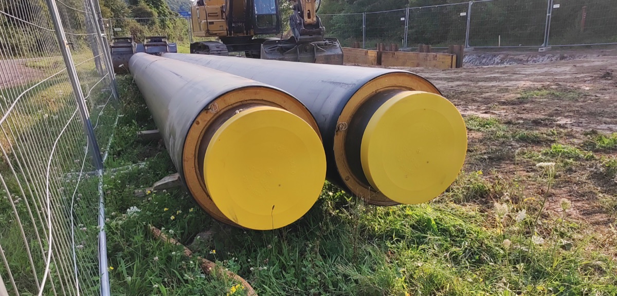
District heating long section — preinsulated pipe in profile
How to draw the longitudinal profile of a district heating network with preinsulated bonded pipe: two diameters (carrier and casing), cover to the casing crown, leak detection, crossings, the profile table and a DXF and IFC export — in the browser, no CAD.
Water main long section to DXF — step by step
How to draw a water main longitudinal profile: minimum cover vs frost depth, pipe centreline levels, valves and hydrants, crossings, the profile table and a clean dual-scale DXF export — in the browser, no CAD.
Sewer long section to DXF — step by step
From field coordinates to a CAD-ready longitudinal profile of a gravity sewer. A concrete walkthrough: import, gradients, manholes, drop connections, dual-scale DXF export.
Ready to design without the pain?
Altivo is the fastest way to produce a clean DXF. Try it today.
Open the free app